Fluid transporter
A technology of fluid transportation and fluid, which is applied in the direction of liquid variable displacement machinery, pumps with flexible working elements, machines/engines, etc., which can solve the problems of difficult accuracy and affecting the accuracy of the amount of liquid delivered, and achieve the improvement of cross-sectional area accuracy and reliability. Occlusion, the effect of improving precision
- Summary
- Abstract
- Description
- Claims
- Application Information
AI Technical Summary
Problems solved by technology
Method used
Image


Examples
Embodiment approach 1
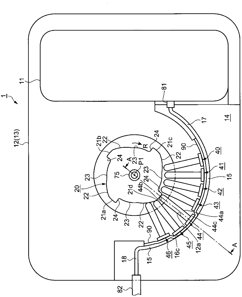
[0041] figure 1 is a plan view showing a part of the fluid transfer device according to Embodiment 1, figure 2 (a) means figure 1 A partial sectional view of the A-P1-A section, figure 2 (b) is a perspective view showing a part of the finger. also, figure 1 It is a function explanatory diagram expressed in perspective of main functional components. exist figure 1 , figure 2 Among them, the fluid delivery device 1 is configured to include: a reservoir 11, which accommodates a liquid medicine; a cam 20, which serves as a rotating body; a flow channel frame 14, which forms a fluid delivery channel 15; and a plurality of pressing members. The fingers 40 to 46 are radially arranged at equal intervals in the direction of the rotation axis P1 of the cam 20 between the transport channel 15 and the cam 20 .
[0042] In addition, although not shown in the figure, the fluid delivery device 1 includes: a drive device as a drive source; a transmission device that transmits the dr...
Embodiment approach 2
[0077] Next, Embodiment 2 will be described with reference to the drawings. Embodiment 2 is characterized in that the cross-sectional shape perpendicular to the fluid flow direction of the channel wall of the transport channel has an arc shape. Therefore, the description will focus on the differences from Embodiment 1, and denote the same functional parts with the same reference numerals. Furthermore, fingers 44 are illustrated.
[0078] Figure 5 (a), Figure 5 (b) represents the fluid transfer device according to Embodiment 2, Figure 5 (a) means figure 1 A partial sectional view of the A-P1-A section, Figure 5 (b) is a perspective view showing part of the finger 44 . exist Figure 5 (a), Figure 5 In (b), the transport channel 15 is formed by the groove 16 formed in the channel frame 14 and the elastic member 90 . The groove 16 is formed by a channel wall 16c having an arc-shaped cross section.
[0079] The finger 44 is composed of a rod-shaped shaft portion 44a,...
Embodiment approach 3
[0088] Next, Embodiment 3 will be described with reference to the drawings. The aforementioned Embodiments 1 and 2 are characterized in that the elastic member forming the transport flow path is in the shape of a thin plate. In contrast, Embodiment 3 is characterized in that the transport flow path is formed by the groove formed in the flow path frame and the elastic member. The peripheral surface of the groove is formed substantially symmetrically. Thus, differences from Embodiment 1 and Embodiment 2 will be described.
[0089] Figure 7 It is a partial cross-sectional view showing the transport channel according to the third embodiment. The transport flow path 15 is formed by the groove 16 formed by the flow path wall 16 c formed in the flow path frame 14 and having an arc-shaped cross section, and the concave portion 91 of the elastic member 90 . The concave portion 91 can be formed by heat embossing, injection molding, or the like of the thin plate-shaped elastic member...
PUM
 Abstract
Description
Claims
Application Information
 - R&D
- Intellectual Property
- Life Sciences
- Materials
- Tech Scout
- Unparalleled Data Quality
- Higher Quality Content
- 60% Fewer Hallucinations
Browse by: Latest US Patents, China's latest patents, Technical Efficacy Thesaurus, Application Domain, Technology Topic, Popular Technical Reports.
© 2025 PatSnap. All rights reserved.Legal|Privacy policy|Modern Slavery Act Transparency Statement|Sitemap|About US| Contact US: help@patsnap.com