Knitting cam for computer flat knitting machine

A computerized flat knitting machine and triangular technology, applied in knitting, weft knitting, textiles and papermaking, etc., can solve problems such as increased difficulty, high processing difficulty, complex structure, etc., and reduce production difficulty, production cost, and manufacturing process requirements Low, the effect of protecting economic interests

Inactive Publication Date: 2012-01-18
浙江海润精工机械有限公司
View PDF8 Cites 0 Cited by
  • Summary
  • Abstract
  • Description
  • Claims
  • Application Information

AI Technical Summary

Problems solved by technology

The knitting cam generally needs to include two tracks, the knitting track and the needle track. The needle track structure of the existing computerized flat knitting machine knitting cam is very complicated, such as the knitting cam disclosed in the utility model patent of application number 201020685549.6. At least five structures such as triangles are stacked, which greatly increases the difficulty of production, and due to the complex structure, the stitches of the knitting needles are easy to hit the related structures in the needle track during the working process of the computerized flat knitting machine, causing damage, breakage, etc. Consequences that seriously affect the economic benefits of users
In addition, the existing weaving triangles are mostly designed in one piece, which is difficult to process

Method used


Image

  • Knitting cam for computer flat knitting machine
  • Knitting cam for computer flat knitting machine
  • Knitting cam for computer flat knitting machine

Examples


Embodiment 1

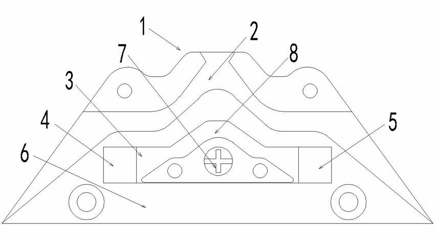
[0014] Embodiment 1: Referring to the accompanying drawings, the weaving cam 1 is left-right symmetrical, and its surface 6 has a weaving track 2. The surface of the weaving cam 1 has an inner cavity 3 between the weaving track 2 and the bottom edge. The inner cavity 3 is convex and has two ends. The first bevel 4 and the second bevel 5 smoothly transition to the surface 6 of the knitting cam 1, and the two sides of the top of the convex character of the inner cavity 3 are inclined to form an acute angle with the horizontal line respectively. Another guide block 7 that is also convex is threaded into the inner cavity 3, the two sides of the bottom end of the guide block 7 and the two sides of the top end are all inclined to form an acute angle with the horizontal line, and the bottom edge of the guide block 7 leans against the inner cavity The bottom edge of 3 can be seen from the figure, and the contact track 8 is formed between the guide block 7 and the top edge of the inner ...

Embodiment 2

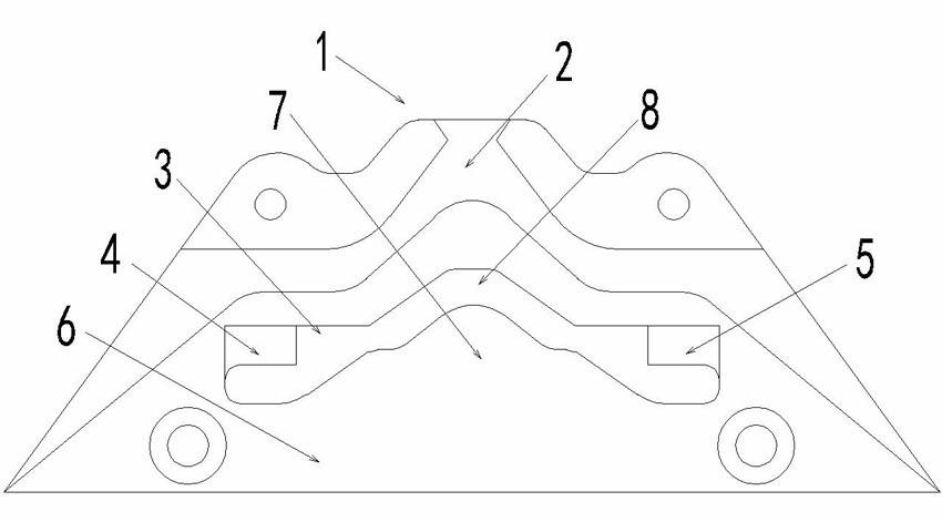
[0015] Embodiment 2: Different from Embodiment 1, the guide block 7 is connected with the braiding cam as a whole.

Embodiment 3

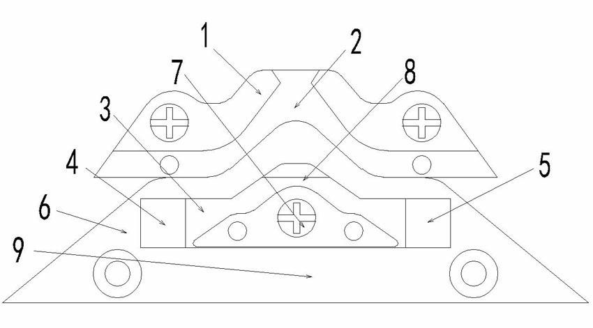
[0016] Embodiment 3: Different from Embodiment 1, the knitting triangle is divided into upper and lower parts, bounded by the bottom edge of the weaving track 2, the upper part is the weaving track block 1, and the lower part is the needle track block 9.


PUM


Abstract

The invention discloses a knitting cam for a computer flat knitting machine, which is fixedly arranged on a cam motherboard, and is characterized in that: a knitting rail is arranged on the surface of the knitting cam, and an inner cavity is arranged between the knitting rail and a bottom edge, and is convex-shaped and bilaterally symmetrical; the two ends are provided with bevels which are in smooth transition to the surface of the knitting cam, and the two sides of the top end of the convex-shaped part of the inner cavity are oblique and respectively have an acute angle with the horizontal line; a bilaterally symmetrical convex-shaped guide block is arranged in the inner cavity, the two sides of the bottom end and the two sides of the top end of the guide block are oblique and respectively have an acute angle with the horizontal line, and the axes of symmetry of the two sides of the bottom end and the top end are coincided; and the left side and the right side of the guide block and the top side of the inner cavity form a back stitch rail. The knitting cam has a simple structure, low manufacturing process requirements, and the production difficulty and the production cost of the computer flat knitting machine are greatly reduced.

Description

technical field [0001] The invention belongs to the technical field of knitting machines, in particular to a knitting cam of a computerized flat knitting machine. Background technique [0002] Computerized flat knitting machine is the most widely used machine in the field of knitting. It generally includes a needle bed mechanism, a pulling mechanism, a knitting system, a transmission mechanism, etc., and the knitting cam system is the key component. The knitting cam generally needs to include two tracks, the knitting track and the needle track. The needle track structure of the existing computerized flat knitting machine knitting cam is very complicated, such as the knitting cam disclosed in the utility model patent of application number 201020685549.6. At least five structures such as triangles are stacked, which greatly increases the difficulty of production, and due to the complex structure, the stitches of the knitting needles are easy to hit the related structures in th...

Claims


Application Information

Patent Timeline
Patent Type & Authority Applications(China)
IPC IPC(8): D04B15/36
Inventor 姚先均王涛
Owner 浙江海润精工机械有限公司
Why Eureka
Try Eureka