
Mobile work machine having support booms

A technology of working machine and cantilever arm, which is applied in the field of drivable working machine with supporting cantilever arm, and can solve the problem that the middle position of the supporting equipment is not allowed.

Inactive Publication Date: 2012-01-11
PUTZMEISTER ENG
View PDF7 Cites 1 Cited by
  • Summary
  • Abstract
  • Description
  • Claims
  • Application Information

AI Technical Summary

Problems solved by technology

The disadvantage here is that intermediate positions of the supporting device according to the site requirements are not permissible

Method used


Image

  • Mobile work machine having support booms
  • Mobile work machine having support booms
  • Mobile work machine having support booms

Examples


Embodiment Construction

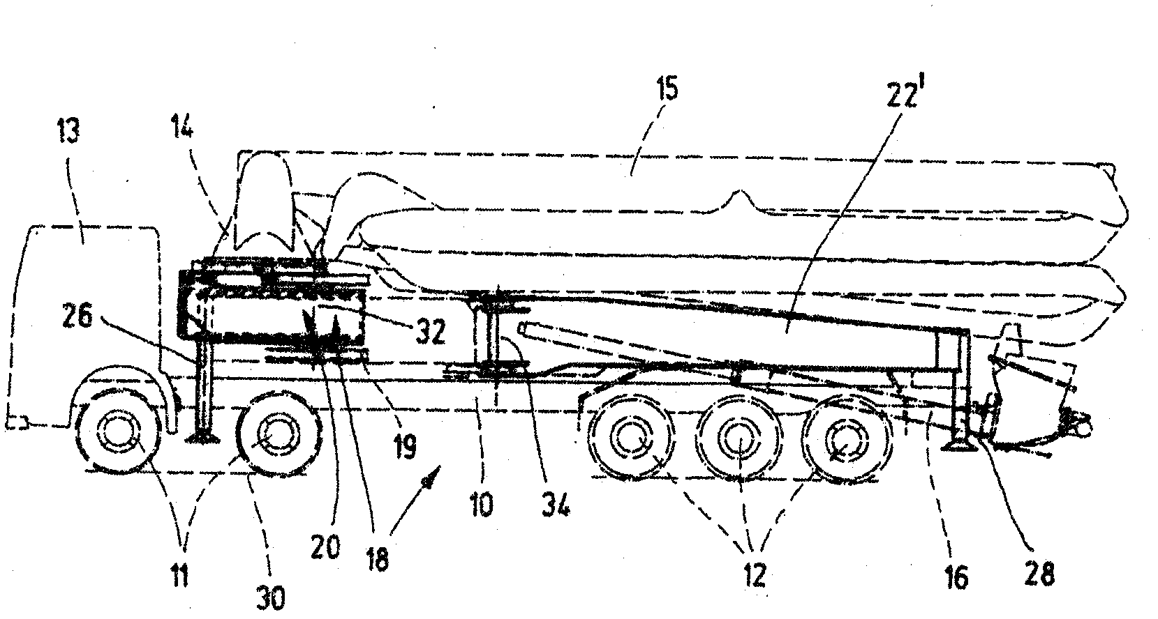
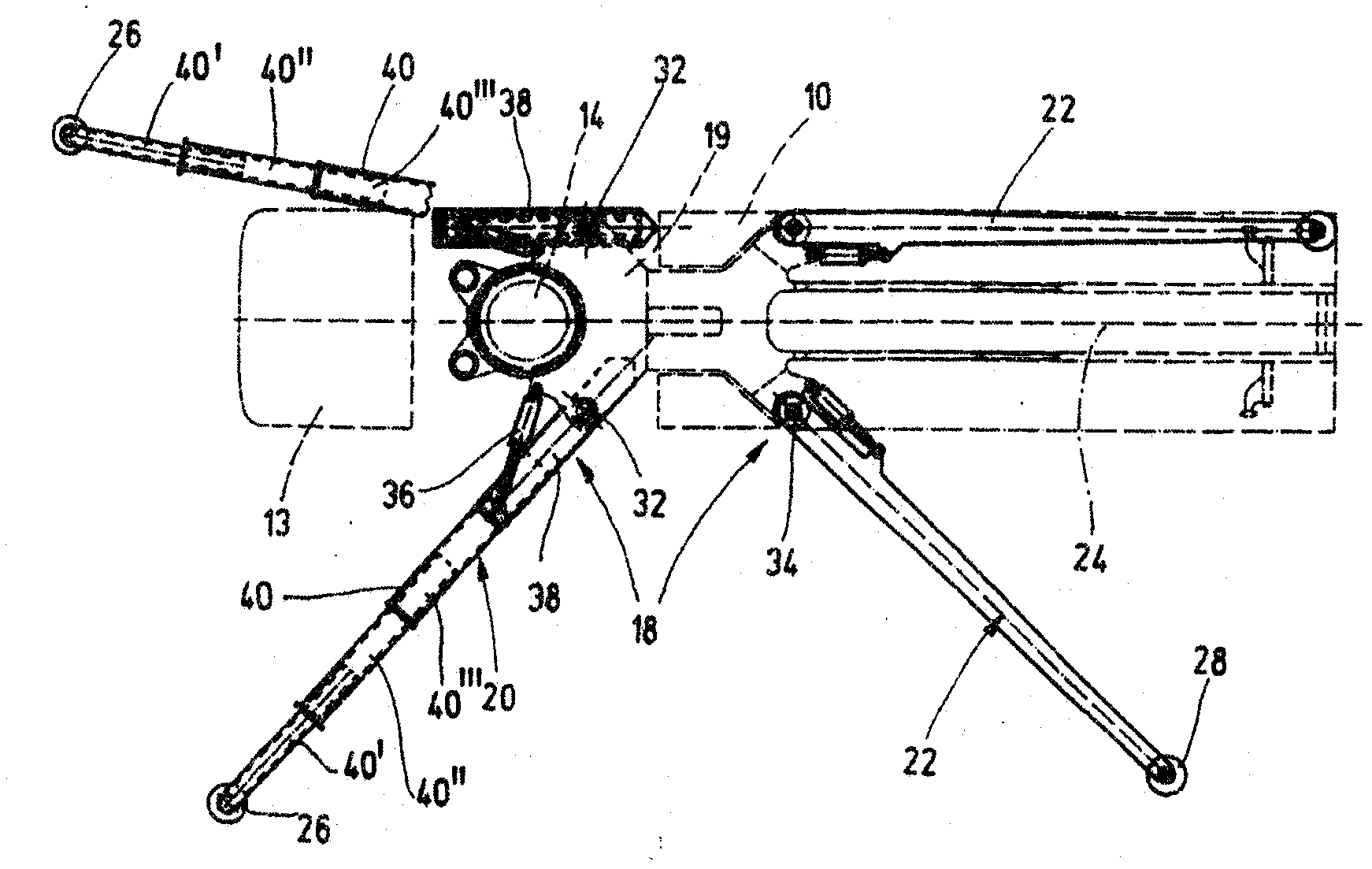
[0017] exist Figure 1a The concrete pump truck shown in b and b mainly includes a multi-axle chassis 10 with two front axles 11 and three rear axles 12 and a driver's cab 13, a rotating mechanism that is rotatably supported around a vertical axis near the front axle The concrete placing boom 15 on 14 has a pump unit 16 mounted on the chassis 10 at a distance from the swivel mechanism 14 and a support structure 18 for the chassis 10. The support structure 18 has a support frame 19 fixed to the chassis and comprises two front support suspension arms 20 and two rear support suspension arms 22 which are folded in the transport position and parallel to the longitudinal axis 24 of the vehicle. Oriented so that the chassis 10 protrudes obliquely forwards or rearwards in the bearing position.

[0018] Under the action of the adjusting cylinders 36, the front support arm 20 is pivotable about its vertical pivot axis 32 and the rear support arm 22 about its vertical pivot axis 34 betwe...


PUM


Abstract

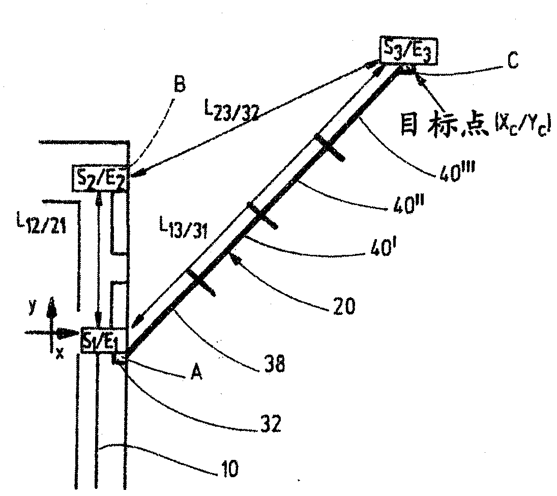
The invention relates to a mobile work machine having a chassis (10) and with two front and two rear support brackets (20, 22). The support brackets can be displaced from a driving position close to the chassis into a support position by changing the base angles ([alpha]) thereof and / or can be telescoped by changing the lengths thereof between the end on the mounting side and that on the free end. In order to be able to automatically determine the support leg positions (Xc / Yc) in relation to the chassis (10), three transceiver units (S1 / E1, S2 / E2, S3 / E3) related to the support legs are provided for transmitting and receiving run time or distance signals. Furthermore, a microprocessor-supported evaluation unit responding to the transmitted and received signals of the transceiver units arranged in pairs is provided, comprising a software routine for determining the support leg positions in a coordinate system (x / y) fixed to the chassis.

Description

technical field [0001] The invention relates to a mobile work machine, which has a chassis and two front support suspension arms and two rear support suspension arms, wherein each support suspension arm is supported by a support side end on a frame fixed to the chassis. On the swivel or sliding joint, the free end of the support cantilever arm carries a telescopic support foot that can be supported on the foundation, and the support cantilever arm can be deflected from a driving position close to the chassis to a support position, Simultaneously a basic angle between the support cantilever and the chassis is varied, and / or the support cantilever is telescopic while simultaneously varying the length of its support cantilever between its support-side end and its free end. Background technique [0002] Mobile working machines of this type are, for example, concrete pump trucks with a concrete distribution boom as a carrier for the conveying pipe, which is articulated with its f...

Claims


Application Information

Patent Timeline
IPC IPC(8): E04G21/04B66C23/90
CPCE04G21/04B66C23/78E04G21/0436B66C23/905B66C23/90B66C13/18E02F3/434
Inventor W-M·佩措尔德M·迈尔D·赫费迈尔
Owner PUTZMEISTER ENG
Learn More