Remote control receiver and projection display device

A technology for receiving devices and remote control signals, which is applied in the directions of telemetry/remote control selection devices, projection devices, selection devices, etc., can solve the problems of complex structure and membership cost, and achieve the effect of simple structure

Inactive Publication Date: 2012-01-11
SANYO ELECTRIC CO LTD
View PDF1 Cites 2 Cited by
  • Summary
  • Abstract
  • Description
  • Claims
  • Application Information

AI Technical Summary

Problems solved by technology

[0006] However, in the above-mentioned structure, since it is necessary to additionally provide a reflection member different from the light guide member, the cost will be correspondingly increased and the structure will be complicated.

Method used


Image

  • Remote control receiver and projection display device
  • Remote control receiver and projection display device
  • Remote control receiver and projection display device

Examples


Embodiment Construction

[0044] Hereinafter, embodiments of the present invention will be described with reference to the drawings.

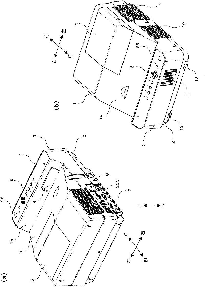
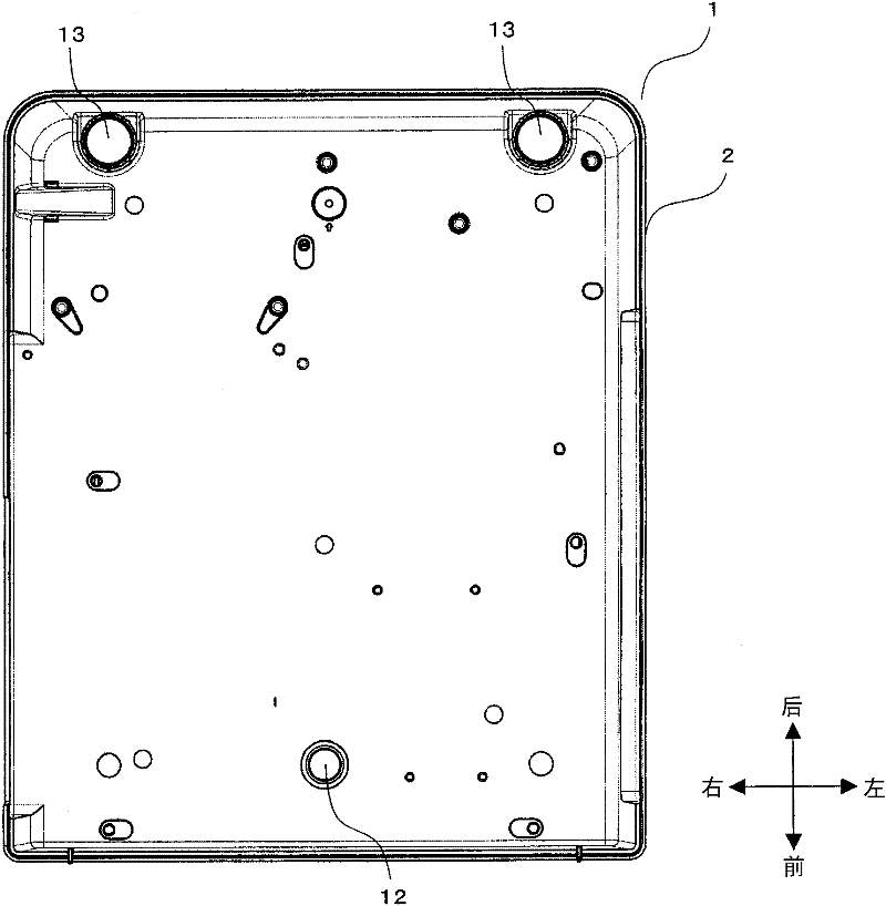
[0045] figure 1 and figure 2 Indicates the appearance structure of the projector. figure 1 (a) is a perspective view of the projector viewed from the front, figure 1 (b) Perspective view of the projector viewed from the rear. in addition, figure 2 is the bottom view of the projector. It should be noted that, for the convenience of explanation, in figure 1 (a), (b) and figure 2 Arrows indicating the front, rear, left, and right directions and arrows indicating the up and down directions are respectively drawn in . Hereinafter, arrows indicating directions are also drawn as necessary in other drawings as well.

[0046] The projector of this embodiment is a so-called short-throw type projector. refer to figure 1 , the projector includes a main body casing 1 having a substantially rectangular parallelepiped shape. The main body case 1 is composed of a lower ca...


PUM


Abstract

The invention provides a remote control receiver receiving emission signals from a wider range with a simple structure. The remote control receiver (25) is provided with: a light-receiving module (401) receiving signal light for remote control; a light guiding member (300) provided with a light receiving surface (301a) receiving the signal light and making the signal light received by the light receiving surface (301a) refract toward the light receiving module (401). Herein, a concave part (303) concaving from the light receiving surface (301a) toward the light receiving module (401) side is formed on the light guiding member (300). Furthermore, the concave part (303) is provided with an inclined plane (303a) toward the concave center.

Description

technical field [0001] The present invention relates to a remote control signal receiving device for receiving transmission signals for remote control. In addition, the present invention also relates to a projection display device including a remote control signal receiving device. Background technique [0002] Conventionally, most projection-type display devices such as liquid crystal projectors (hereinafter referred to as "projectors") are equipped with a remote control signal receiving device, and remote control can be performed by a transmission signal (for example, signal light based on infrared rays) from a remote control transmitter. distance operation. [0003] In the case where the projector is installed on the floor or a table, it is considered that remote operations are accepted from the front, back, left, and right of the device. Usually, the angle range that the remote control signal receiving device can receive is not so wide. Therefore, in order to receive ...

Claims


Application Information

Patent Timeline
IPC IPC(8): G08C23/00G03B21/00G03B21/14H04N5/00H04N5/74H04Q9/00
CPCG03B21/145G08C23/04H04N9/3141
Inventor 久保敦志吉川努吉村太一
Owner SANYO ELECTRIC CO LTD
Why Eureka
Try Eureka