
Air conditioner

A technology for an air conditioner and a motor, which is applied to air conditioning systems, space heating and ventilation, heating methods, etc., can solve the problem that the overlapping part becomes larger, the size of the arrangement direction of the first fan motor 116 and the first fan 115 cannot be reduced, and the wind loss Increase and other problems to achieve the effect of reducing wind loss

Inactive Publication Date: 2012-01-11
DAIKIN IND LTD
View PDF8 Cites 4 Cited by
  • Summary
  • Abstract
  • Description
  • Claims
  • Application Information

AI Technical Summary

Problems solved by technology

[0007] However, in the above-mentioned conventional air conditioner, the above-mentioned first fan 115 is located on the side of the first suction port 112 of the first duct 110 compared to the above-mentioned first fan motor 116, so it is necessary to separate the first fan 115 and the first fan motor 116. The motor 116 is completely accommodated in the first duct 110, so that the size of the first duct 110 in the direction in which the first fan motor 116 and the first fan 115 are arranged, that is, the front-to-back direction cannot be reduced.
[0008] Moreover, the above-mentioned first fan 115 is located closer to the first suction port 112 of the first duct 110 than the first fan motor 116, and the distance between the first fan 115 and the partition wall 113 in the direction perpendicular to the axis of the first fan 115 The overlapping portion becomes larger, most of the wind blown from the first fan 115 hits the partition wall 113, and the wind loss increases

Method used


Image

  • Air conditioner
  • Air conditioner
  • Air conditioner

Examples


Embodiment Construction

[0024] Hereinafter, the present invention will be described in detail based on the illustrated embodiments.

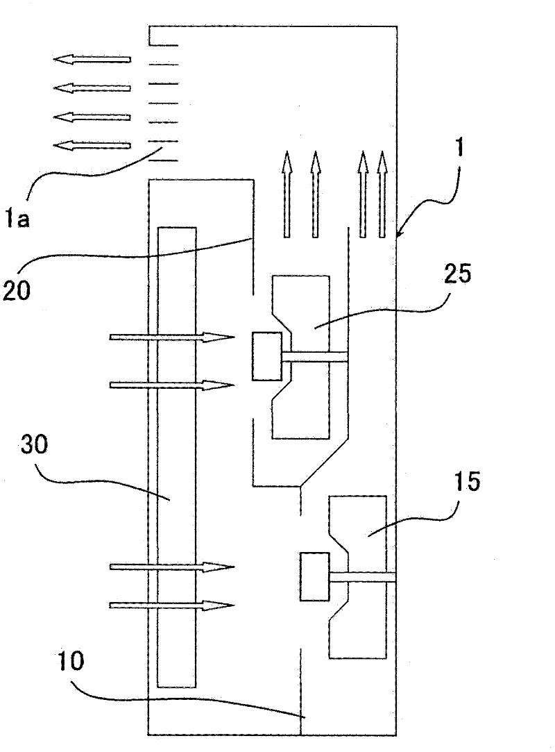
[0025] figure 1 It is a schematic sectional view which shows the air cleaner which is one Embodiment of the air conditioner of this invention. Such as figure 1 As shown, the air cleaner has a casing 1 and a first duct 10 and a second duct 20 arranged in the casing 1 . The first duct 10 constitutes the first air passage 10 , and the second duct 20 constitutes the second air passage 20 .

[0026] The first duct 10 and the second duct 20 are arranged in parallel and point in the same direction. The first duct 10 is positioned behind the second duct 20 .

[0027] The first duct 10 and the second duct 20 are partially overlapped, and a common partition member 14 is used for the overlapping portion. That is, the partition member 14 partitions the first air passage 10 and the second air passage 20 .

[0028] The first outlet 11 of the first duct 10 and the second outl...


PUM


Abstract

The invention relates to an air conditioner. Specifically, the invention provides an air conditioner which has a small size and reduces the wind loss. As a solution means, a first pipeline (10) and a second pipeline (20) are arranged vertically in a juxtaposing way. On the lower side of the first pipeline (10), a first fan (15) is located farther away from a first suction inlet (12) of the first pipeline (10) than a first fan motor (16) is. Therefore, the majority of the wind from the first fan (15) will not be blown towards a partition wall (13) but avoid the partition wall (13).

Description

technical field [0001] The present invention relates to air conditioners such as air cleaners and fan coils, for example. Background technique [0002] In the past, as an air conditioner, such as image 3 As shown, there is an air conditioner in which a first duct 110 and a second duct 120 pointing in the same direction are arranged side by side in a casing 101 (refer to Patent Document 1: Japanese Patent Laid-Open No. 2008-32387). [0003] Such as image 3 As shown, the first outlet 111 of the first duct 110 and the second outlet 121 of the second duct 120 open toward the upper side of the casing 101 . The first suction port 112 of the first duct 110 and the second suction port 122 of the second duct 120 open toward the front of the casing 101 . [0004] A first fan 115 and a first fan motor 116 for driving the first fan 115 are accommodated in the first duct 110 . A second fan 125 and a second fan motor 126 for driving the second fan 125 are housed in the second duct 120...

Claims


Application Information

Patent Timeline
IPC IPC(8): F24F1/00
Inventor 坂下朗彦皇甫吏英山下哲也早田圭吾
Owner DAIKIN IND LTD
Learn More