
Novel tensioning transmission device

A transmission device and tensioning device technology, which is applied in the field of new tensioning transmission devices, can solve the problems of chain disconnection, loss of function, easy stretching and lengthening, etc., and achieves the improvement of work efficiency, improvement of cleaning effect, and reduction of friction Effect

Inactive Publication Date: 2012-01-11
马瑞奥食品加工系统(北京)有限公司
View PDF6 Cites 13 Cited by
  • Summary
  • Abstract
  • Description
  • Claims
  • Application Information

AI Technical Summary

Problems solved by technology

[0004] However, the use of this transmission device has certain disadvantages: first, when the cleaning medium reaches a certain temperature, the pins of the plastic keel chain chain itself are easy to fall off, causing the chain to be out of joint; second, when the cleaning medium reaches a certain temperature, the plastic keel The chain itself is easy to stretch and become longer, and slips with the driving wheel, which directly affects the transmission: third, there is sliding friction between the plastic keel chain and the guide rail, which affects the service life of the chain and guide rail; fourth, the plastic keel chain automatically The tensioning device of the belt will lose its function when the chain is stretched to a certain length; the above reasons cause the plastic keel chain itself to be unable to adapt to the high temperature disinfection standard of the food industry

Method used


Image

  • Novel tensioning transmission device
  • Novel tensioning transmission device
  • Novel tensioning transmission device

Examples


Embodiment Construction

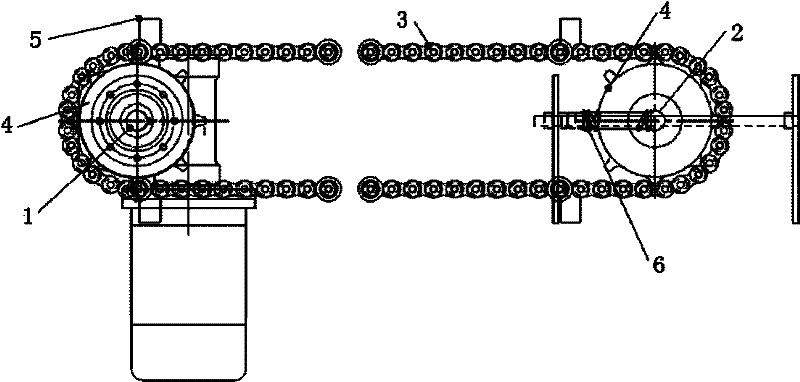
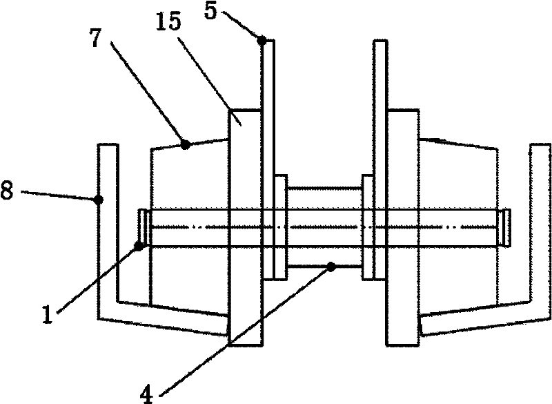
[0016] Such as figure 1 , 2 As shown, a novel tension transmission device of the present invention comprises a chain 3, a guide rail 8, a driving shaft 1 and a driven shaft 2 driven by a driving device, and the middle of the driving shaft 1 and the driven shaft 2 are respectively fixed with Sprocket 4, the two ends are fixed with the guide wheel 7 that matches with described guide rail 8, between described sprocket 4 and guide wheel 7, be fixed with push box finger 5, described driven shaft 2 is provided with spring tensioner. Tightening device 6.

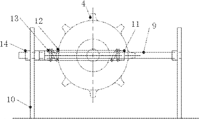
[0017] Such as figure 1 , 3 4. The spring tensioning device 6 shown in 4 includes two fixing plates 10, two lead screws 9 fixed in the middle of the fixing plates 10, and the lead screws 9 pass through the end of the driven shaft 2; Located at one end of the driven shaft 2, a fixed nut 11 mounted on the lead screw 9, located at the other end of the driven shaft 2, a compression spring 12 mounted on the lead screw 9, the compres...


PUM


Abstract

The invention provides a novel tensioning transmission device capable of realizing the automatic tensioning without artificial regulation on the tightness of a chain, which comprises a guide rail, a driving shaft and a driven shaft, wherein the driving shaft and the driving shaft are driven by a driving device, chain wheels are respectively fixedly arranged in the middles of the driving shaft and the driven shaft, both ends of the driving shaft and the driven shaft are fixed with guide wheels matched with the guide rail, box pushing pulling fingers are fixed between the chain wheels and the guide wheels, and a spring tensioning device is arranged on the driven shaft. The novel tensioning transmission device adopts the stainless steel chain, the device per se cannot be influenced by the temperature, and the temperature of the cleaning media can be raised to be higher than the sterilization temperature specified by the food industry. The tightness of the chain can be effectively regulated through the spring tensioning device, so the transmission device can more perfectly act. The transmission device has the advantages that rolling friction is adopted between the guide wheels and the guide rail, the friction is greatly reduced, and the service life of the chain and the service life of the guide rail are prolonged. After the new belt tensioning transmission device is adopted, the cleaning effect can be improved by about 50 percent, simultaneously, the fault rate is reduced, in addition, the maintenance is convenient, and the work efficiency is improved by about one time.

Description

technical field [0001] The invention relates to a transmission device, in particular to a novel tension transmission device. Background technique [0002] At present, in the domestic slaughtering industry, plastic keel chain chain transmission is generally used in box cleaning equipment. [0003] The usual conveying chain is a motor-driven conveying structure on the box cleaning equipment, which is directly sprayed and washed by the nozzle built in the equipment during the conveying process. First, the nozzle is built into the equipment, and then during the transmission process, the box is sprayed through the nozzle built in the equipment, so as to clean out the meat scraps, meat residues and other impurities remaining on the box. [0004] However, the use of this transmission device has certain disadvantages: first, when the cleaning medium reaches a certain temperature, the pins of the plastic keel chain chain itself are easy to fall off, causing the chain to be out of jo...

Claims


Application Information

Patent Timeline
IPC IPC(8): B65G23/44
Inventor 李业新
Owner 马瑞奥食品加工系统(北京)有限公司
Learn More