
Self-priming pump capable of applying fertilizer

A self-priming pump and pump body technology, applied in the field of liquid conveying equipment, can solve the problems of inconvenient use, long self-priming time, and small exhaust capacity, and achieve the effects of convenient use, short self-priming time and high efficiency

Inactive Publication Date: 2012-01-04
重庆市丰收农机制造有限公司
View PDF6 Cites 1 Cited by
  • Summary
  • Abstract
  • Description
  • Claims
  • Application Information

AI Technical Summary

Problems solved by technology

[0002] Irrigation and fertilization in agricultural production are usually carried out separately. Centrifugal pumps are generally used for irrigation. The characteristics of the pump body are simple structure and high pumping efficiency. The existing centrifugal pumps generally include a pump body, a pump shaft and an impeller. Among them, the pump body There are a water inlet chamber, a water outlet chamber and an impeller working chamber on the top. The water inlet chamber communicates with the water outlet chamber through the impeller working chamber. The impeller is installed on the pump shaft and located in the impeller working chamber. The centrifugal pump with this structure is very suitable for agricultural production. It is widely used, but in the process of use, it needs to fill the pump body and the 7-8 meter long pipeline connecting the pump body and the water source with water and empty the air. The amount of water is large, the time is long, and the use is inconvenient
[0003] Self-priming pump, there is no need to install a bottom valve on the water inlet pipe of the self-priming pump. When using it for the first time, you only need to pour a small amount of water into the pump casing, and the pump body can suck the water out. Compared with centrifugal pumps, the operation is simpler, but existing The structure of the self-priming pump is relatively complex, the exhaust capacity is small, and the self-priming time is long.

Method used


Image

  • Self-priming pump capable of applying fertilizer
  • Self-priming pump capable of applying fertilizer
  • Self-priming pump capable of applying fertilizer

Examples


Embodiment Construction

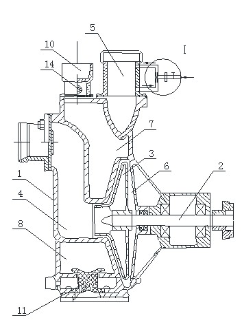
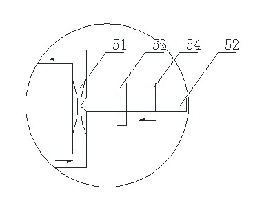
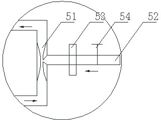
[0013] Such as figure 1 and figure 2 As shown, the present invention provides a fertilizing self-priming pump, which includes a pump body 1, a pump shaft 2 and an impeller 3, wherein the pump body 1 is provided with a water inlet chamber 4, a water outlet chamber 5, an impeller working chamber 6, and a water filling chamber. chamber 7 and exhaust chamber 8, the water inlet chamber 4 communicates with the water outlet chamber 5 through the impeller working chamber 6, the impeller 3 is installed on the pump shaft 2 and is located in the impeller working chamber 6, and the water adding chamber 7 communicates with the water outlet chamber 5 through a hole, The mouth 10 of the water filling chamber 7 is provided with a one-way valve 15; the exhaust chamber 8 communicates with the impeller working chamber 6, and the mouth of the exhaust chamber 6 is provided with a backflow stop valve 11, and the pump body 1 is also provided with a drain valve. The water discharge channel communic...


PUM


Abstract

The invention relates to a liquid conveying device, and in particular relates to a self-priming pump capable of applying a fertilizer. The self-priming pump comprises a pump body, a pump shaft and impellers, wherein the pump body is provided with a water inlet cavity, a water outlet cavity, an impeller working cavity, a water replenishing cavity and an air exhaust cavity; the water inlet cavity is communicated with the water outlet cavity via the impeller working cavity; the impellers are mounted on the pump shaft and are positioned in the impeller working cavity; the water replenishing cavity is communicated with the water outlet cavity via holes on the pump body; and the opening of the water replenishing cavity is provided with a one-way valve; the air exhaust cavity is communicated with the impeller working cavity; the opening of the air exhaust cavity is provided with a backflow stop valve; the pump body is further provided with a water draining channel communicated with the air exhaust cavity; the water draining channel is sealed by a water-draining nut; the outlet of the water outlet cavity is provided with a segment of communication pipe connected in parallel with the outlet; the inner tube diameter at the central part of the communication pipe first tapers and then gradually expands; and the central part of the communication pipe is provided with a fertilizer feeding pipe. By adopting the self-priming pump according to the technical scheme, irrigation and fertilizer application can be simultaneously realized, and the self-priming pump is easy to use and has the advantages of high efficiency and short self-priming time.

Description

technical field [0001] The invention relates to a liquid conveying device, in particular to a fertilizing self-priming pump. Background technique [0002] Irrigation and fertilization in agricultural production are usually carried out separately. Centrifugal pumps are generally used for irrigation. The characteristics of the pump body are simple structure and high pumping efficiency. The existing centrifugal pumps generally include a pump body, a pump shaft and an impeller. Among them, the pump body There are a water inlet chamber, a water outlet chamber and an impeller working chamber on the top. The water inlet chamber communicates with the water outlet chamber through the impeller working chamber. The impeller is installed on the pump shaft and located in the impeller working chamber. The centrifugal pump with this structure is very suitable for agricultural production. It is widely used, but in the process of use, it needs to fill the pump body and the 7-8 meter long pip...

Claims


Application Information

Patent Timeline
Patent Type & Authority Applications(China)
IPC IPC(8): F04D9/02
Inventor 陈彪
Owner 重庆市丰收农机制造有限公司
Learn More