Luffing tower crane with balanced type suspension arm based on traction luffing of steel rope
A technology of luffing jib tower cranes and traction transformers, applied in cranes and other directions, can solve problems such as poor lifting performance and large additional bending moments, and achieve the effects of weight reduction, traction force and additional bending moments
- Summary
- Abstract
- Description
- Claims
- Application Information
AI Technical Summary
Problems solved by technology
Method used
Image

Examples
Embodiment 1
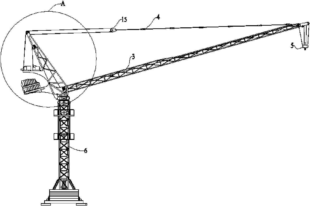
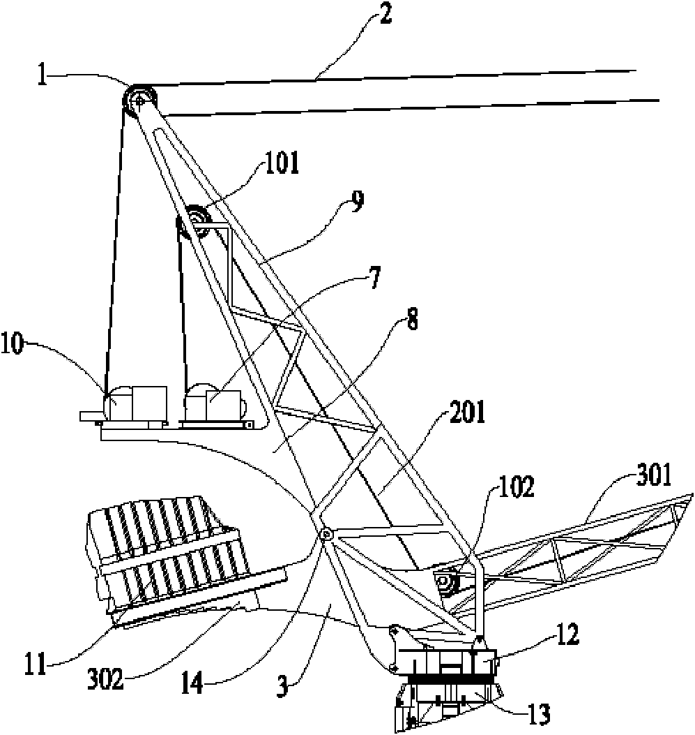
[0043] see in conjunction figure 1 and figure 2 , the boom balanced luffing jib tower crane based on steel rope traction and luffing in a preferred embodiment of the present invention includes a tower body 6, a lower support 13 installed on the top of the tower body 6, a slewing support 12 is installed on the lower support 13, and A tower top 9 is installed on the top of the slewing support 12 . A boom 3 , a balance arm 8 , a hoisting mechanism 7 and a luffing mechanism 10 are installed on the tower top 9 . A counterweight 11 and a hook assembly 5 are installed on the boom 3 . The luffing steel rope 2 of the luffing mechanism 10 is connected to the boom 3 through the pull rod group 4 .
[0044] Wherein, the boom 3 includes a lifting end 301 and a boom counterweight end 302 opposite to the lifting end 301 to form an integral composite structure. The end portion of the lifting end 301 of the boom 3 includes a hook assembly 5 installed, and the end portion of the counterweig...
Embodiment 2
[0050] Figure 5 A modified structure of the preferred embodiment 1 of the present invention is shown. It can be seen from the figure that the difference between it and Embodiment 1 is that the balance arm 8 in Embodiment 1 is canceled, wherein the luffing mechanism 10 is installed on the top of the tower top 9, and a pulley support is provided at the corresponding position on the top of the tower top 9 16. The luffing fixed pulley 1 is installed in the pulley support 16, and the lifting fixed pulley 101 is installed at the hinge point 14. In addition, the lifting mechanism 7 is directly installed on the counterweight end 302 of the boom 3 .
[0051] It can be seen from the description of Embodiment 2 that, compared with Embodiment 1, the structure of the tower top 9 is simplified because the balance arm 8 is omitted from the tower top 9 . Since the hoisting mechanism 7 is directly installed on the counterweight end 302 of the boom 3, the self weight of the hoisting mechanis...
Embodiment 3
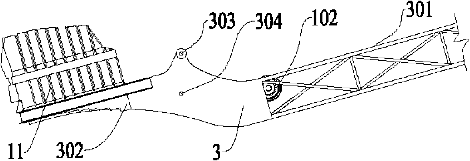
[0053] Figure 6 and Figure 7 Another modified structure of the preferred embodiment 1 of the present invention is shown. As can be seen from the figure, the difference between it and Embodiment 1 is that the boom 3 is provided with a hollow structure 303 adjacent to the counterweight end 302, and the hollow structure 303 forms a hollow rectangular cavity along the center of the boom 3, and the lower end of the tower top 9 It can move through the hollow rectangular cavity, and two coaxial hinge seats 304 are provided on both lateral sides of the hollow rectangular cavity. .
[0054] From the description of Embodiment 3, it can be seen that, compared with Embodiment 1, the boom 3 is provided with a hollow structure 301 adjacent to the counterweight end 302, and the hollow structure 301 is contained in the tower top 9 and passes through the hinge seat of the boom 3 304 is hinged at the hinge point 14 of the tower top 9 . In this way, structurally, the distance between the h...
PUM
 Abstract
Description
Claims
Application Information
 - R&D
- Intellectual Property
- Life Sciences
- Materials
- Tech Scout
- Unparalleled Data Quality
- Higher Quality Content
- 60% Fewer Hallucinations
Browse by: Latest US Patents, China's latest patents, Technical Efficacy Thesaurus, Application Domain, Technology Topic, Popular Technical Reports.
© 2025 PatSnap. All rights reserved.Legal|Privacy policy|Modern Slavery Act Transparency Statement|Sitemap|About US| Contact US: help@patsnap.com