
Sludge drying process and equipment

A sludge drying and equipment technology, applied in the direction of dehydration/drying/concentrated sludge treatment, etc., can solve the problem of difficult breakthrough in the gelation process of the drying process, the reduction of the heat exchange effect between the blade shaft and the raw material, and the reduction of equipment processing capacity, etc. problems, to achieve the effect of controllable sludge drying degree, high sludge treatment efficiency, and reduced voltage fluctuation

Inactive Publication Date: 2011-12-28
SUZHOU ZILI CHEM EQUIP
View PDF4 Cites 9 Cited by
  • Summary
  • Abstract
  • Description
  • Claims
  • Application Information

AI Technical Summary

Problems solved by technology

[0003] (1) The structure of the cylinder in the equipment is simple, difficult to maintain, and it is difficult to adjust the discharge speed according to the degree of sludge drying during the implementation of the drying process;
[0004] (2) When the internal structure of the paddle shaft in this equipment uses steam as the heating medium, steam-water mixing is prone to occur, thereby blocking the steam inlet between the hollow shaft and the hollow paddle, resulting in a great heat exchange effect between the paddle shaft and the raw material Decrease, and cause equipment processing capacity to decline;
[0005] (3) The structure of the equipment is easy to cause the sludge to agglomerate during the drying treatment process, resulting in overload shutdown during the operation of the equipment, and it is difficult to break through the gelation process in the drying process

Method used


Image

  • Sludge drying process and equipment
  • Sludge drying process and equipment
  • Sludge drying process and equipment

Examples


Embodiment Construction

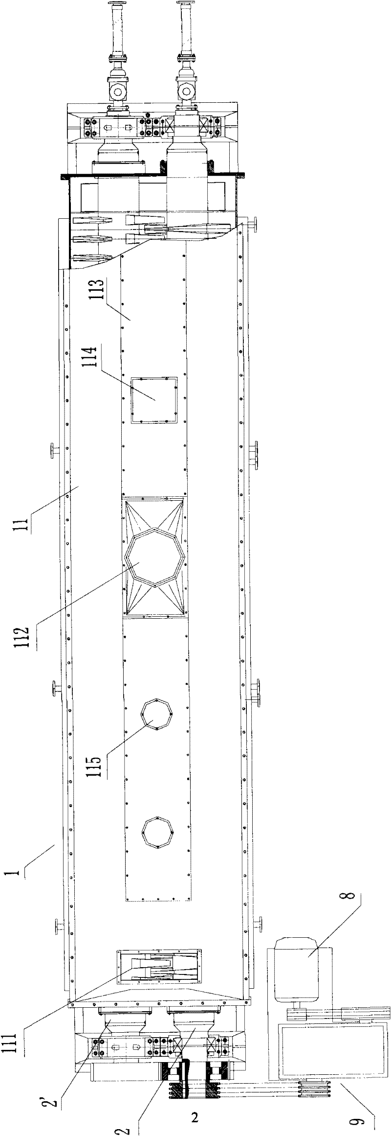
[0034] like figure 1 As shown, the steps included in the sludge drying process are:

[0035] (1) Pretreat the sludge with a water content above 80% to a water content below 50%, keep the temperature of the sludge constant, and input it from a feed port 111 (A to) a sludge drying equipment 1 ;

[0036] (2) In the above-mentioned sludge drying equipment 1, the sludge is continuously pushed to the discharge port 121, and the sludge is heated to above 120°C, accompanied by continuous stirring and crushing treatment, and at the same time, the sludge The volatilized water vapor in the mud is continuously drawn out from the steam outlet 112 until the sludge with the desired moisture content is discharged from the sludge drying equipment (direction B).

[0037] The above-mentioned tail gas generated by the water vapor drawn from the sludge dryer by the air-inducing equipment is input into the incineration system after the dust removal treatment. The specific method of the dust remov...


PUM


Abstract

The invention relates to a sludge drying process and equipment. The process is: pretreat the sludge with high moisture content until the moisture content is lower than the set value, keep the temperature of the sludge constant, and input it into the sludge drying equipment, in which the sludge is continuously discharged to the It is pushed by the mouth, and the sludge is heated to above 120°C, accompanied by continuous stirring and crushing, and at the same time, the water vapor volatilized from the sludge is continuously drawn out by the air-inducing equipment until the sludge with the required moisture content is produced. The sludge is discharged from the drying equipment. The sludge drying equipment is produced for the improvement of the traditional hollow paddle dryer. The process of the present invention is simple and easy to operate, runs smoothly, and can make the degree of sludge drying more controllable, the sludge treatment capacity is larger, and there is no risk of secondary pollution; the equipment of the present invention has simple structure, stable operating performance, and high efficiency. High, and can achieve the goal of energy saving and emission reduction, it is expected to be widely used in the field of environmental protection and in chemical, pharmaceutical, food and other industries.

Description

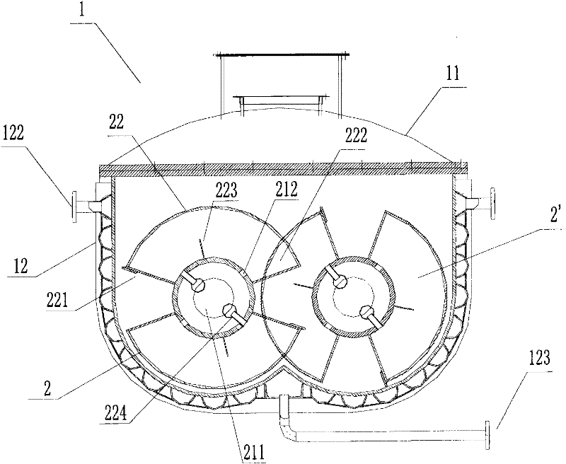
technical field [0001] The invention specifically relates to a process and equipment applicable to dry treatment of various kinds of sludge generated in urban life and industrial production, as well as various raw materials in chemical industry, pharmaceutical raw materials, food processing and other industries. Background technique [0002] With the continuous advancement of urbanization and the development of modern industry, a huge amount of various types of urban domestic sludge and industrial sludge are produced every year in the world. For this reason, people have developed a variety of processes to treat these sludges in order to achieve the goal of recycling, but in these processes, sludge drying is generally a necessary step. At present, the hollow paddle dryer usually used in the sludge drying process mainly includes a cylinder, a paddle shaft arranged in the cylinder, a drive and a transmission device; wherein, the cylinder is composed of an approximately W-shaped...

Claims


Application Information

Patent Timeline
IPC IPC(8): C02F11/12
Inventor 马雪明王世兴
Owner SUZHOU ZILI CHEM EQUIP
Learn More