Working elements that can be adapted to various shaft ends

A technology of working elements and shaft ends, applied in the field of working elements, can solve the problems of lack of versatility, unusable working elements, and inability to install multi-function tools, and achieves the effect of reducing manufacturing costs and simplifying process procedures

Inactive Publication Date: 2011-12-28
NANJING CHERVON IND
View PDF9 Cites 17 Cited by
  • Summary
  • Abstract
  • Description
  • Claims
  • Application Information

AI Technical Summary

Problems solved by technology

[0003] At present, there are several brands of multi-function tools on the market, such as DREMEL, FEIN, and WORX. Each brand of multi-function tool is equipped with its own brand of working components, but the working components of each brand cannot be used in common, that is, Say, when a user purchases a certain brand of multi-function tool, if he needs to purchase a replaceable working element, he can only buy the working element of this brand, and the working element of other brands cannot be installed in the multi-function tool he owns. superior
Therefore, the existing working elements do not have good versatility, which brings troubles to users

Method used


Image

  • Working elements that can be adapted to various shaft ends
  • Working elements that can be adapted to various shaft ends
  • Working elements that can be adapted to various shaft ends

Examples


Embodiment approach 1

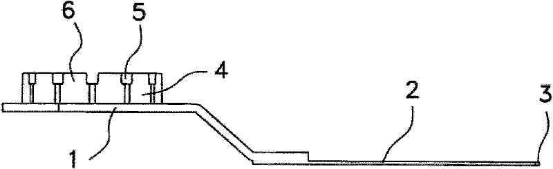
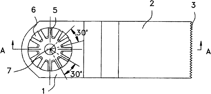
[0039] Such as Figure 1 to Figure 7 As shown, a saw blade, a working element commonly used on oscillating tools, is taken as a preferred embodiment. The saw blade includes a body part 2 and a support part 1 connected to the body part for fitting to the shaft end of a multifunctional tool. The front end of the body part 2 includes a sawtooth area 3 that can act on the workpiece to be processed to realize cutting. An adapter part 4 is provided on the support part 1 of the saw blade. The adapter part 4 and the support part 1 are integrally formed. Of course, in other implementations In the manner, the adapter part 4 may also be fixedly connected to the support part 1 by welding, riveting, screwing or other suitable connection methods. The support part 1 and the adapter part 4 form a clamping part for connecting the saw blade to the tool shaft end. The end surface of the adapter part 4 is provided with a plurality of radially penetrating grooves 5 and a plurality of protrusions ...

Embodiment approach 2

[0048] Such as Figure 8-14 Shown is the saw blade according to the second preferred embodiment of the present invention. The saw blade includes a body part 2 and a support part 1 connected to the body part. The front end of the body part 2 includes a sawtooth area suitable for acting on the workpiece to realize cutting. 3. An adapter portion 4 suitable for adapting to various shaft ends is welded on the support portion 1 of the saw blade. The support part 1 is provided with a mounting hole 7 with a longitudinal central axis Y, and a fastener such as a screw passes through the mounting hole and is connected to the shaft end when the saw blade is fixed to the shaft end. The adapter part 4 is provided with a positioning hole 310 that can limit the circumferential rotational displacement of the saw blade relative to the shaft end. The longitudinal axis of the positioning hole 310 coincides with the longitudinal central axis Y of the mounting hole 7, so that the circumferential ed...

Embodiment approach 3

[0054] Such as Figure 15 As shown, the difference between the third embodiment and the second embodiment is that the adapter part 4 in this embodiment is directly connected to the main body part 2 through the connecting handle 41 , and the support part 1 is directly connected to the adapter part 4 by welding. As for the fitting structure of the fitting part 4 , the installation structure of the supporting part 1 , and the welding connection process of the fitting part 4 and the supporting part 1 , they are all the same as those in the second embodiment, and will not be repeated here.


PUM


Abstract

The invention provides a working component capable of being fit with various shaft ends. The working component comprises a body portion and a clamping portion supporting portion which is connected with the body portion and is suitable to install the working component on the shaft end, wherein the body portion is provided with a cutting edge zone workpiece processing zone acting on a workpiece to be processed; a clamping portion is provided with an installation hole; and the installation hole is provided with a longitudinal axis Y. The working component is characterized in that the clamping portion comprises the supporting portion and a fit portion; and the fit portion and the supporting portion are superposed along the direction of the longitudinal axis Y. The working component has the following beneficial effects: the working component can be fit with shaft ends in various shapes; meanwhile, the fit portion is directly arranged on the supporting portion of the working component, thus reducing the accessories of multifunction tools and ensuring the multifunction tools to have portability; and as the fit portion adopts the manufacturing process of punch forming, compared with the previous process of indispensable die-casting forming, the manufacturing process of punch forming is beneficial to reduction of the manufacturing cost and simplification of the process procedures.

Description

technical field [0001] The invention relates to a working element, in particular to a working element for fitting onto the shaft end of an output shaft capable of being driven by oscillation. Background technique [0002] At present, there are some multifunctional tools with replaceable working elements on the tool market. The replaceable working elements are installed on the output shaft end of the multifunctional tool, so that the multifunctional tool has multiple uses, and thus can be applied to various working occasions. The multi-function tool is also called an oscillating tool. Its working principle is: a motor driver is installed in the body of the multi-function tool, and the eccentric output shaft installed in the spherical bearing is driven by a shift fork to make an oscillating motion, thereby driving the working element to make an oscillating motion , to realize the processing of the workpiece to be processed. Different working elements have different special pu...

Claims


Application Information

Patent Timeline
Patent Type & Authority Applications(China)
IPC IPC(8): B25F5/00
CPCB23D61/006B25F1/00B24B23/04B24B45/00B24B27/08B27B5/32Y10T279/33Y10T279/3406
Inventor 张晓峰张百军
Owner NANJING CHERVON IND
Why Eureka
Try Eureka