
Automatic loading and unloading device for vehicles and automatic loading and unloading vehicle

An automatic loading and unloading, vehicle technology, applied to vehicles with cranes, vehicles with swing arms, etc., can solve problems such as waste of financial resources, human and material resources and time, high requirements for master cylinder synchronization, and potential safety hazards. The effect of a gentle lowering, opening or closing process and increased overall structural stability

Inactive Publication Date: 2011-12-21
SANY HEAVY IND CO LTD (CN)
View PDF6 Cites 3 Cited by
  • Summary
  • Abstract
  • Description
  • Claims
  • Application Information

AI Technical Summary

Problems solved by technology

In the traditional mode of operation, the joint operation of lifting equipment and transport vehicles is often used to carry the mobile silo, which causes various wastes of financial resources, manpower, material resources and time. There are also problems in the following aspects:
[0003] 1) In the lifting stage, the combination of the auxiliary cylinder and the main cylinder is used to add a control method, and when the auxiliary cylinder is disengaged, the lifting arm is prone to vibration to a certain extent, which poses a safety hazard
[0004] 2) The main oil cylinder is directly connected to the lifting arm, which requires high synchronization of the two main oil cylinders, and it is difficult to achieve precise control

Method used


Image

  • Automatic loading and unloading device for vehicles and automatic loading and unloading vehicle
  • Automatic loading and unloading device for vehicles and automatic loading and unloading vehicle
  • Automatic loading and unloading device for vehicles and automatic loading and unloading vehicle

Examples


Embodiment Construction

[0023] The following will clearly and completely describe the technical solutions in the embodiments of the present invention with reference to the accompanying drawings in the embodiments of the present invention. Obviously, the described embodiments are only some, not all, embodiments of the present invention. Based on the embodiments of the present invention, all other embodiments obtained by persons of ordinary skill in the art without making creative efforts belong to the protection scope of the present invention.

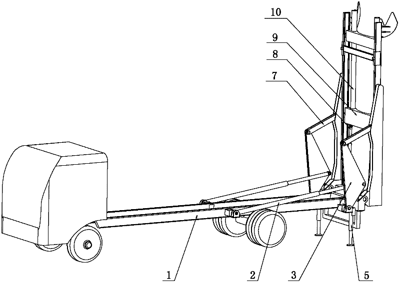
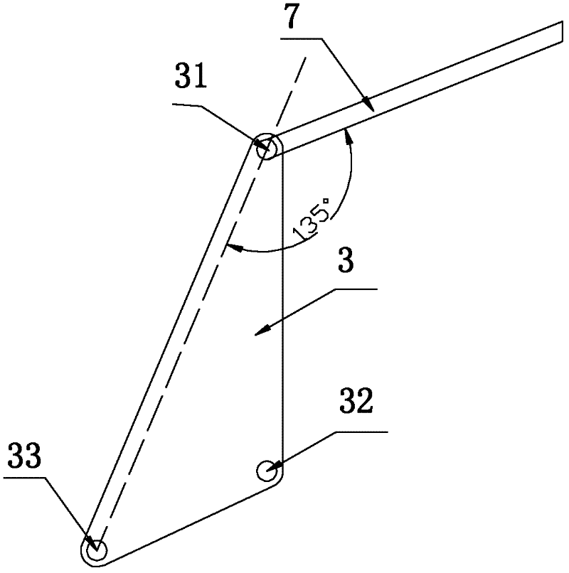
[0024] Such as Figure 1 to Figure 3 As shown, an automatic loading and unloading device for vehicles provided by the present invention includes a lifting mechanism and a loading and unloading mechanism. , the loading and unloading mechanism also includes an undercarriage 3 and a support link 7, and the undercarriage 3 includes such as image 3 The first hinge hole 31 shown, the second hinge hole 32 and the third hinge hole 33, the third hinge hole 33 is hing...


PUM


Abstract

The invention relates to an automatic loading and unloading device for vehicles and an automatic loading and unloading vehicle. The automatic loading and unloading device comprises a lifting mechanism and a loading and unloading mechanism, wherein loading and unloading mechanisms are connected to the two sides of the lifting mechanism respectively and comprise a main oil cylinder, a landing gear and a supporting connecting rod respectively; the landing gear comprises a first hinge hole, a second hinge hole and a third hinge hole; the third hinge hole is hinged with a chassis of a tank-transport truck; one end of the main oil cylinder is hinged with the second hinge hole, and the other end of the main oil cylinder is hinged with the chassis of the tank-transport truck; and one end of the supporting connecting rod is hinged with the first hinge hole, and the other end of the supporting connecting rod is hinged with the lifting mechanism. Since the structure of the landing gear and the supporting connecting rod is adopted, a connecting rod mechanism is formed between the landing gear as well as the supporting connecting rod and the main oil cylinder as well as the lifting mechanism, and thrust force of the main oil cylinder is uniformly acted on a lifting arm; and thus, the lifting arm is slowly and stably opened or folded, and the defect of large shock produced by the lifting arm during releasing of an auxiliary oil cylinder and acting of the main oil cylinder existing in the prior art is avoided.

Description

technical field [0001] The invention relates to an automatic loading and unloading device, in particular to an automatic loading and unloading device for vehicles. In addition, the present invention also relates to an automatic loading and unloading vehicle equipped with the automatic loading and unloading device. Background technique [0002] At present, most of the construction mortar used in my country's construction industry uses a bulk mobile silo storage device, which is used together with a continuous mixer and often operates between the construction site and the dry mixing station. In the traditional mode of operation, the joint operation of lifting equipment and transport vehicles is often used to carry the mobile silo, which causes various wastes of financial resources, manpower, material resources and time. There are also problems in the following aspects: [0003] 1) In the lifting stage, the combination of the auxiliary oil cylinder and the main oil cylinder i...

Claims


Application Information

Patent Timeline
Patent Type & Authority Applications(China)
IPC IPC(8): B60P1/48B60P1/54
Inventor 郭兰满刘国庆周铁刚
Owner SANY HEAVY IND CO LTD (CN)
Learn More