
A New Type Integrated Flywheel and Clutch Transmission Mechanism

A kind of transmission mechanism and integrated technology, applied in the direction of transmission device, transmission device parts, mechanical equipment, etc., can solve the problems of large mechanism, high cost, unfavorable use of space, etc., and achieve the effect of overcoming high cost

Inactive Publication Date: 2011-12-14
韩继玲
View PDF0 Cites 0 Cited by
  • Summary
  • Abstract
  • Description
  • Claims
  • Application Information

AI Technical Summary

Problems solved by technology

[0002] In mechanical transmission, the flywheel as the input mechanism of power and the clutch of the control mechanism of power transmission are generally independent of each other. As a result, the result is that the mechanism is relatively large, which is not conducive to effective use of space. At the same time, this structure The transmission system still has the limitation of high cost

Method used


Image

  • A New Type Integrated Flywheel and Clutch Transmission Mechanism
  • A New Type Integrated Flywheel and Clutch Transmission Mechanism
  • A New Type Integrated Flywheel and Clutch Transmission Mechanism

Examples


Embodiment approach

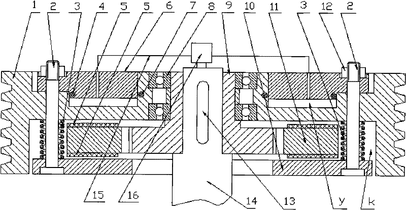
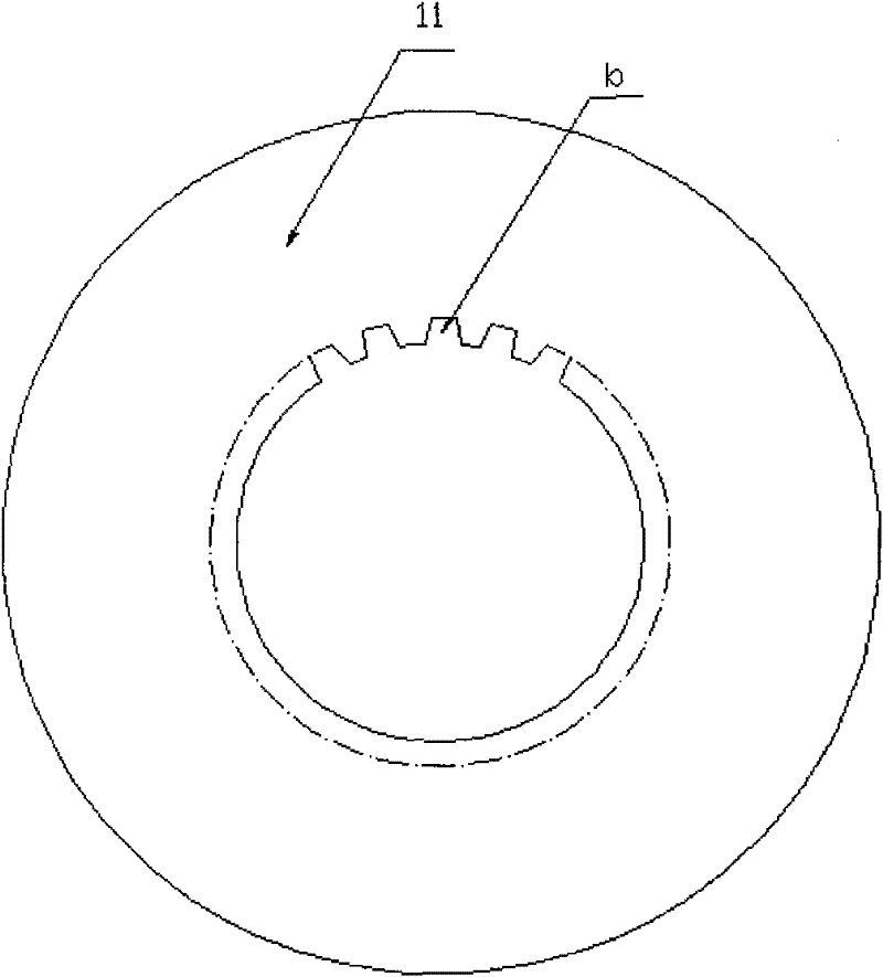
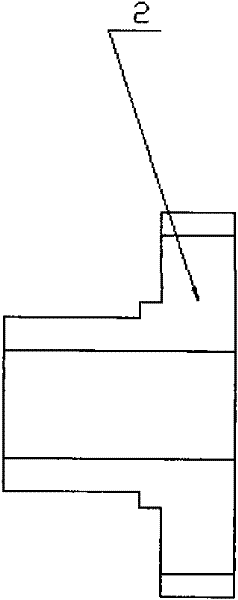
[0014] The integrated flywheel and clutch transmission mechanism has a driving body (9), and the driving body (9) is installed on the transmission shaft (14) with a key (13), forming a connection relationship between the driving body (9) and the transmission shaft (14); The driving body (9) has two outer circles, large and small, and convex and concave teeth (a) are evenly distributed on the large outer circle of the driving body (9). The two sides of the driving disc (11) are equipped with friction plates ( 5), a round hole is made in the center of the driving disc (11), and concave-convex teeth (b) similar to those on the outer circle of the driving body (9) are made on the inner surface of the round hole, and the driving disc (11) passes through The concave-convex teeth (b) on the inner circle are engaged with the concave-convex teeth (a) on the outer circle of the driving body (9), and there are concave-convex teeth (a), ( b) Degree of freedom of relative sliding; cylinder...


PUM


Abstract

A new type of integrated flywheel and clutch transmission mechanism, which is composed of two large and small outer circles of the driving body, convex and concave teeth are evenly distributed on the large outer circle of the driving body, and the two sides of the driving disc are riveted. A round hole is made in the center of the drive disc, and concave-convex teeth similar to those on the outer circle of the driver are made on the inner surface of the round hole. On the concave and convex teeth, the cylinder and the drive disc chamber are respectively manufactured on both sides of the flywheel. The drive disc chamber faces the direction of the drive disc, and the flywheel is installed on the small outer circle of the drive body with the gear shaft, and the piston is installed on the mouth of the cylinder on the side of the flywheel. , the piston and the cylinder are respectively sealed by the inner sealing ring of the cylinder and the outer sealing ring of the cylinder, an adjusting nut is screwed on one end of the tie rod, the rotary air intake joint is installed at the center of the head of the driving body, and the intake and exhaust pipes are respectively connected with the inner cavity of the cylinder Connects to the swivel air inlet fitting.

Description

Technical field: [0001] The invention relates to a transmission mechanism, in particular to a novel integrated flywheel and clutch transmission mechanism, which belongs to the technical field of mechanical transmission. Background technique: [0002] In mechanical transmission, the flywheel as the input mechanism of power and the clutch of the control mechanism of power transmission are generally independent of each other. As a result, the result is that the mechanism is relatively large, which is not conducive to effective use of space. At the same time, this structure There is also a disadvantage of high cost in the transmission system. Invention content: [0003] The purpose of the present invention is to provide a new type of integrated flywheel and clutch transmission mechanism, which overcomes the disadvantages of the existing transmission mechanism due to the independent structure of the flywheel and the clutch: the transmission mechanism is relatively large, which ...

Claims


Application Information

Patent Timeline
Patent Type & Authority Applications(China)
IPC IPC(8): F16H33/02F16H57/00
Inventor 韩继玲
Owner 韩继玲
Learn More