
an engine shock absorber

A shock absorber and engine technology, which is applied in the direction of spring/shock absorber, mechanical equipment, vibration suppression adjustment, etc., can solve the problems of weakened engine parts, hindering the work of surrounding instruments and equipment, and operator fatigue, etc., and achieve improvement Comfort, overcoming strength weakening, and prolonging the service life

Active Publication Date: 2011-12-14
HUBEI INST OF AEROSPACE CHEMOTECHNOLOGY
View PDF5 Cites 4 Cited by
  • Summary
  • Abstract
  • Description
  • Claims
  • Application Information

AI Technical Summary

Problems solved by technology

Severe vibration will weaken the strength of engine parts, increase wear, reduce life span, and make operators tired, hinder the work of surrounding instruments and equipment, and pollute the environment

Method used


Image

  • an engine shock absorber
  • an engine shock absorber
  • an engine shock absorber

Examples


Embodiment Construction

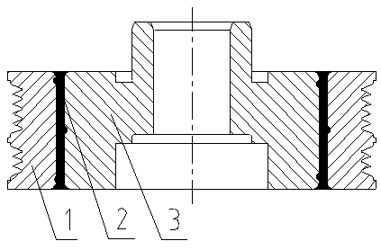
[0015] figure 1 Among them, the present invention consists of an outer ring 1, a rubber part 2 and a connecting part 3. The connecting piece 3 has a spiral circular groove, and the outer ring 1 has a spiral circular groove in the opposite direction. The rubber part 2 is located between the outer ring 1 and the connecting piece 3 . Belt grooves can be set on the outer ring 1 as required. The direction of rotation of the helical circular grooves on the connecting piece, the outer ring, must be opposite.

[0016] The rubber part 2 is molded by vulcanization, and the rubber part 2 is embedded between the outer ring 1 and the connecting part 3 by a press-fitting process.

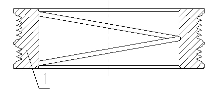
[0017] figure 2 Among them, a helical circular groove is provided on the inner peripheral surface of the outer ring 1 .

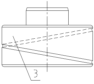
[0018] image 3 Among them, a helical circular groove is provided on the outer peripheral surface of the connector 3 .


PUM


Abstract

The invention provides a vibration damper for an engine, comprising an external ring, a connecting piece, and a rubber piece disposed between the external ring and the connecting piece; the external periphery of the connecting piece is provided with a helical annular groove; the external circumference of the external ring is provided with a helical annular groove corresponding to the groove on the connecting piece. The rubber piece is pressed to the space between the external ring and the connecting piece via a press mounting mode, making the external ring, the rubber piece, and the connecting piece form a firm integral body. The vibration damper for an engine can effectively reduce destruction brought by torsional vibration of a crankshaft of the engine, and improve driving comfortableness of conductors and drivers.

Description

technical field [0001] The invention relates to an automobile engine vibration reduction technology. Background technique [0002] Vibration is unavoidable when the engine is running. This is because the gas pressure in the combustion chamber and the inertial force of the moving mass of the crank linkage are both periodic functions related to the rotational period of the engine crankshaft. Therefore, the torsional moment generated by them to rotate the crankshaft, the overturning moment of the engine, the inertial force acting along the centerline of the cylinder, and the inertial force in the horizontal direction are also periodic functions. Under the action of periodically changing forces and moments, the engine will vibrate both vertically and horizontally. Severe vibration will weaken the strength of engine parts, increase wear, reduce life span, and make operators tired, hinder the work of surrounding instruments and equipment, and pollute the environment. Contents ...

Claims


Application Information

Patent Timeline
IPC IPC(8): F16F15/126
Inventor 刘洪
Owner HUBEI INST OF AEROSPACE CHEMOTECHNOLOGY
Learn More