


Quick Research
Generate reliable direction feasibility study reports for your R&D in just a few steps.

Technical Q&A
Discover and master advanced knowledge NOW. Basics, ideas, possibilities, all at once.

Find Solutions
As an expert in R&D theories, this can generate solutions to your technical problems instantly.

Evaluate Feasibility
Analyze your overall solution with one click, know your potential R&D risks in advance.

Monitor Landscape
Get weekly tech updates, stay abreast of the latest tech innovations and key insights.
tube target
A tube target and carrier tube technology, which is applied in the field of tube targets, can solve problems such as damage, no longer covering, and target damage.
- Summary
- Abstract
- Description
- Claims
- Application Information
AI Technical Summary
Problems solved by technology
Method used
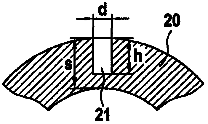
Image

Examples
Embodiment Construction
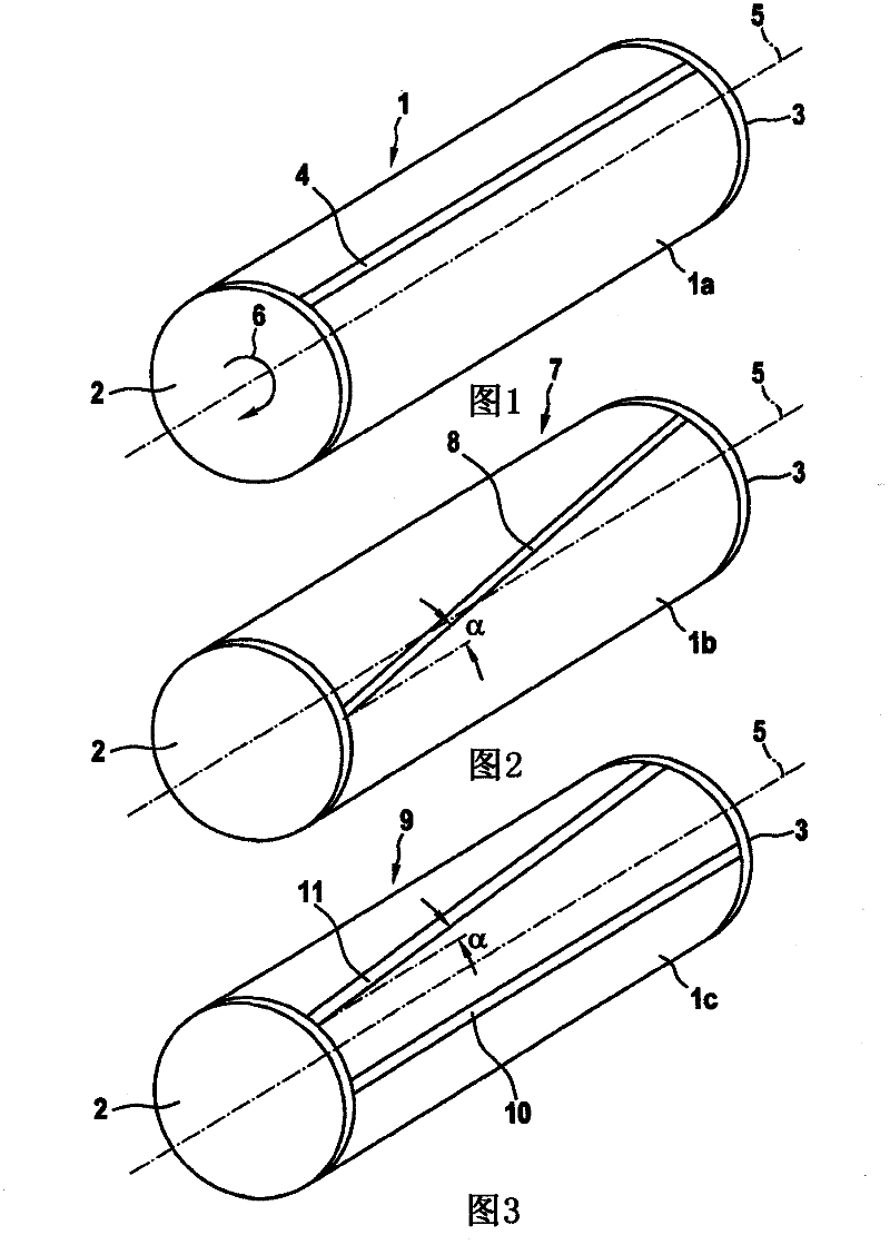
[0029] exist figure 1 The tube target 1 is shown schematically in a perspective view. For the sake of simplicity, the tube target is closed here with caps 2 , 3 . Tube Target 1 has the figure 1 The carrier tube surrounded by the target 1a is not visible in . The target 1 a is provided with a groove 4 which extends parallel to the axis of rotation 5 of the tube target 1 . The direction of rotation is indicated briefly by arrow 6 . The depth of the groove 4 is not fixed.
[0030] A plasma is present during the sputtering process above or below a portion of the tube target 1 . The plasma is substantially as long as the tube target 1 , but has a diameter smaller than the diameter of the tube target 1 . If the tube target 1 is rotated, the slot 4 is above or below the plasma for the entire length of the slot during the under or over coating of the plasma. The slot 4 immersing in the plasma, staying in the plasma or leaving from the plasma changes the plasma-facing surface of...
PUM
 Abstract
Description
Claims
Application Information
 - R&D Engineer
- R&D Manager
- IP Professional
- Industry Leading Data Capabilities
- Powerful AI technology
- Patent DNA Extraction
Browse by: Latest US Patents, China's latest patents, Technical Efficacy Thesaurus, Application Domain, Technology Topic, Popular Technical Reports.
© 2024 PatSnap. All rights reserved.Legal|Privacy policy|Modern Slavery Act Transparency Statement|Sitemap|About US| Contact US: help@patsnap.com