
Engine crankcase oil and gas pre-filter

An oil-gas pre-filter and pre-filter technology, which is applied in the direction of engine components, crankcase ventilation, machines/engines, etc., can solve the problems of large oil-gas flow resistance, increased crankcase pressure, and low separation efficiency, so as to avoid oil-gas short circuit, The effect of accelerating the airflow velocity and avoiding the dead angle of oil return

Inactive Publication Date: 2011-12-07
GUANGXI YUCHAI MASCH CO LTD
View PDF6 Cites 0 Cited by
  • Summary
  • Abstract
  • Description
  • Claims
  • Application Information

AI Technical Summary

Problems solved by technology

[0004] The oil and gas pre-filtration device of the existing engine mostly adopts a simple labyrinth structure or directly blocks the steel wire ball, the pre-filtration efficiency of the oil and gas is low, the separated engine oil is difficult to recover, the filter element in the oil-gas separator is frequently replaced, and the user cost is high
The disadvantage of the traditional labyrinth technology scheme is that it adopts a tortuous circulation structure. If the tortuousness is too large, the oil and gas flow resistance will be large and the crankcase pressure will increase; if the tortuousness is too small, the oil and gas adsorption area will be too small and the separation efficiency will be low.
There is no air flow acceleration separation structure, and the separation effect on large and small oil and gas particles is not good
It is difficult to deal with the backflow of accumulated oil in the labyrinth

Method used


Image

  • Engine crankcase oil and gas pre-filter
  • Engine crankcase oil and gas pre-filter
  • Engine crankcase oil and gas pre-filter

Examples


Embodiment Construction

[0024] A specific embodiment of the present invention will be described in detail below in conjunction with the accompanying drawings, but it should be understood that the protection scope of the present invention is not limited by the specific embodiment.

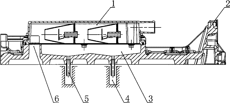
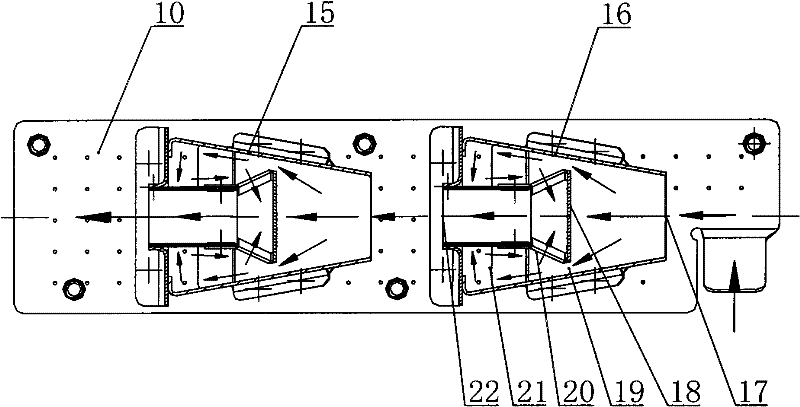
[0025] The filtering principle of the oil-gas pre-filter of the present invention is to use the principle that the airflow will accelerate when the airflow channel is narrowed from the width, that is, the flow velocity in the narrowed section will increase. as attached image 3 As shown, the oil-gas channel inside the labyrinth assembly of the present invention is narrowed from the width. At this time, the oil-gas flow accelerates, and the large-particle oil droplets have a large inertia due to their large mass. , so as to adhere to the inner wall of the pre-filter; the pre-filtration of small particles of oil droplets passing through the secondary labyrinth component will also be reduced to a certain extent.

[0026] The...


PUM


Abstract

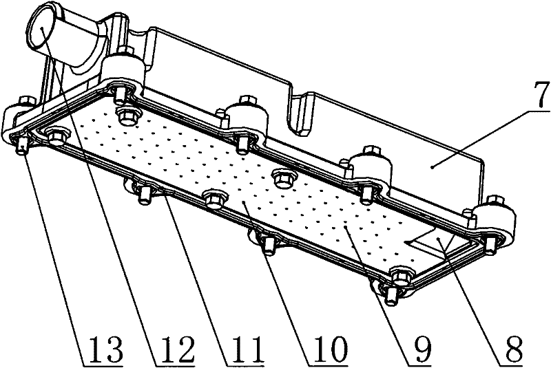
The invention discloses an engine crankcase oil-gas pre-filter, which is installed above the oil-collecting chamber of a cylinder head cover, and comprises a pre-filter cover, a pre-filter bottom plate and a labyrinth assembly, and the labyrinth assembly is installed on the pre-filter cover and the pre-filter bottom plate In the enclosed space; the labyrinth component is a frustum-shaped cavity structure, and there is an annular constriction channel in the cavity, and a labyrinth swirl cavity is located on the rear side of the annular constriction channel; the pre-filter oil and gas inlet is set on the pre-filter bottom plate, and the pre-filter oil and gas The inlet is communicated with the air port on the cylinder head cover, and the oil and gas outlet is arranged on the pre-filter cover; the oil-passing hole is set on the bottom plate of the pre-filter. The oil-gas pre-filter of the present invention has a more compact pre-filter structure, smoother oil return and better oil-gas pre-separation effect.

Description

technical field [0001] The invention relates to an oil-gas separation device, in particular to an oil-gas pre-filter for an engine crankcase. Background technique [0002] The exhaust gas burned by the internal combustion engine will leak into the crankcase through the piston ring gap during the working process, and there is a large amount of combustible fuel gas in the exhaust gas. However, it is generally discharged directly into the atmosphere after simple separation, which causes waste first, and pollutes the environment second. [0003] The national automobile emission standard stipulates that after the implementation of the National Three Standards, the engine crankcase exhaust gas cannot be directly discharged into the atmosphere, and the crankcase forced ventilation scheme must be used: after the exhaust gas is treated, it is introduced into the air filter, mixed with fresh air before the supercharger, and then enters The combustion chamber is involved in the combus...

Claims


Application Information

Patent Timeline
IPC IPC(8): F01M13/04
Inventor 庞威赵贵
Owner GUANGXI YUCHAI MASCH CO LTD
Learn More