
Catalytic cracking technology and device for reducing olefins in gasoline

A catalytic cracking device and catalytic cracking technology, applied in catalytic cracking, cracking, petroleum industry, etc., can solve the problems of inflexible control of catalyst temperature, low catalyst-to-oil ratio, and low coking capacity of the device

Active Publication Date: 2013-10-02
CHINA PETROCHEMICAL CORP +1
View PDF3 Cites 0 Cited by
  • Summary
  • Abstract
  • Description
  • Claims
  • Application Information

AI Technical Summary

Problems solved by technology

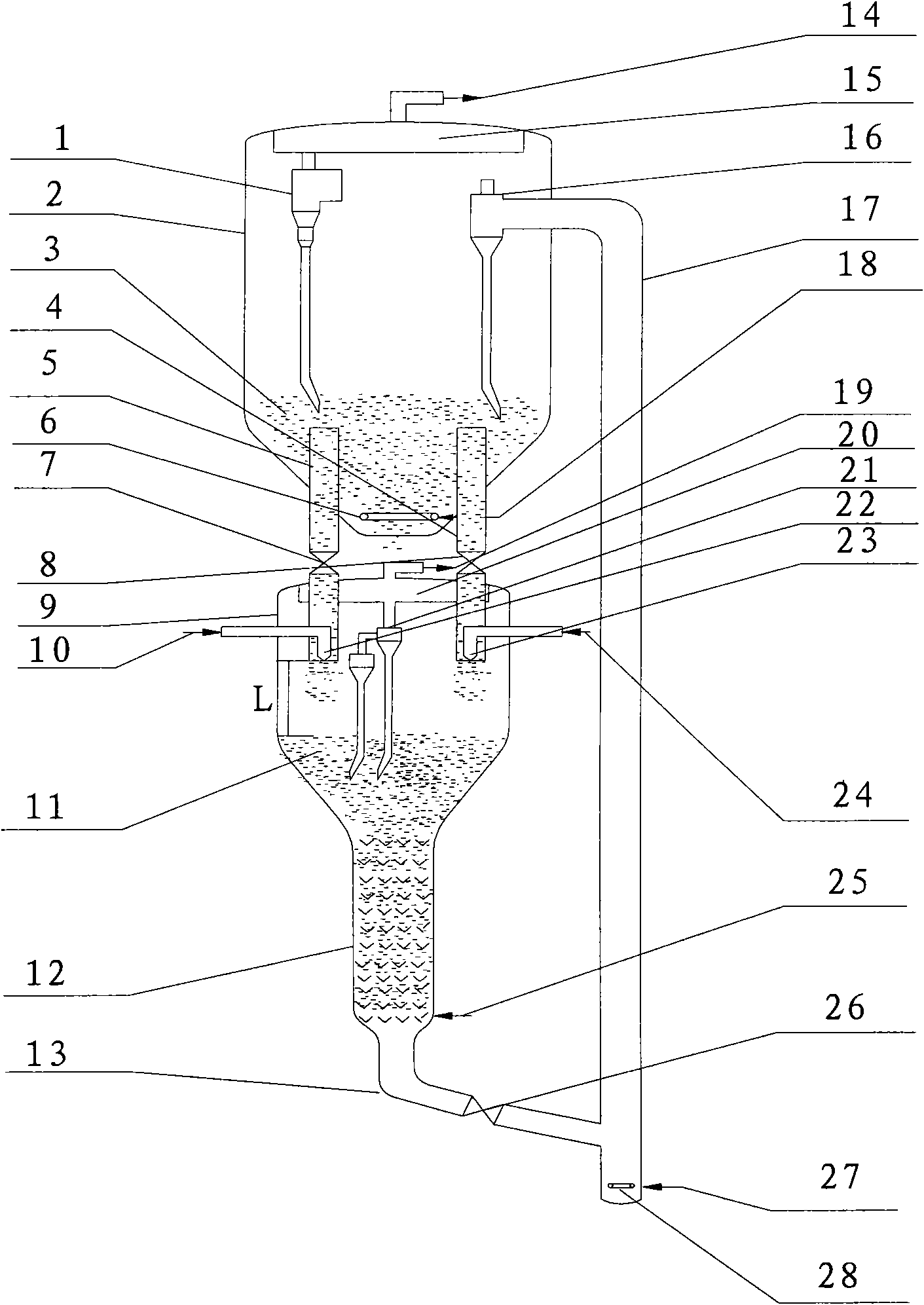
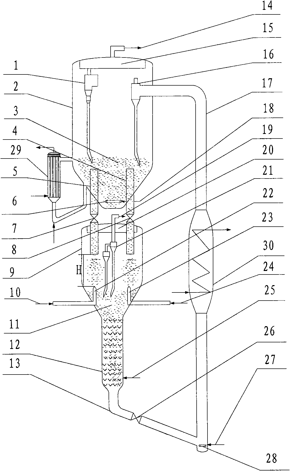
[0009] The technical problem to be solved by the present invention is that in the existing catalytic cracking process, the temperature of the catalyst in the regenerator cannot be flexibly controlled, the contact temperature between the regenerated catalyst and the raw material is high, the reaction time is long, the ratio of catalyst to oil is low, and the coking capacity of the device is low, etc.

Method used


Image

  • Catalytic cracking technology and device for reducing olefins in gasoline
  • Catalytic cracking technology and device for reducing olefins in gasoline
  • Catalytic cracking technology and device for reducing olefins in gasoline

Examples


Embodiment 3

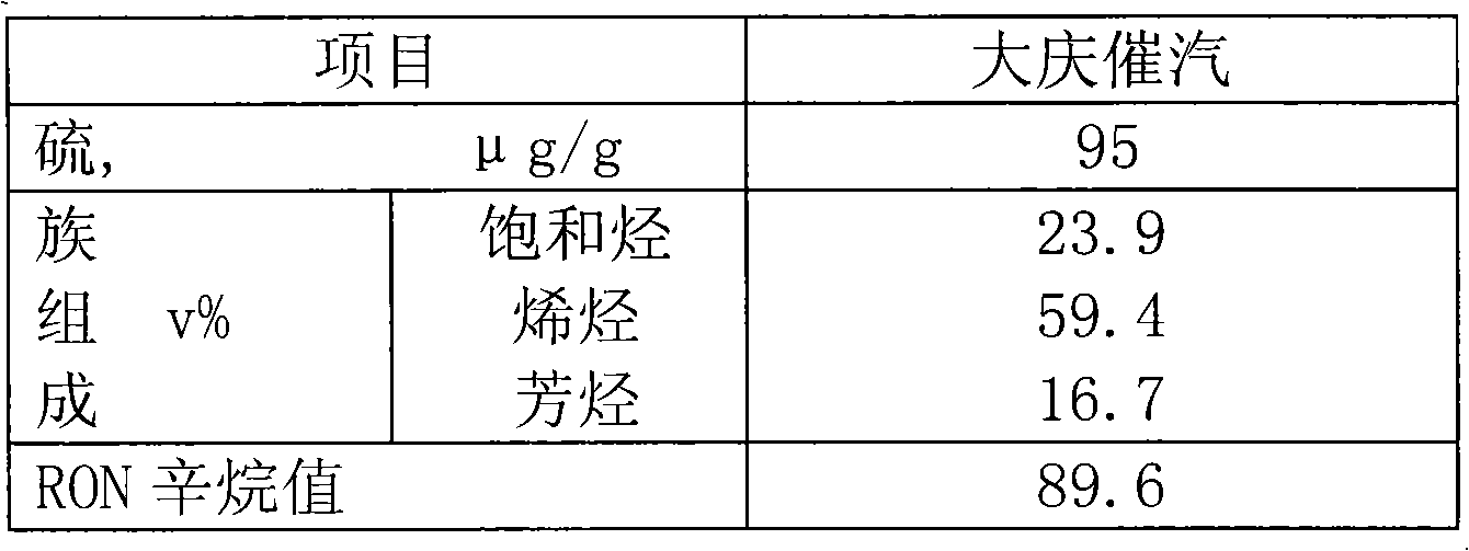
[0073] The raw material used in the test was atmospheric residual oil from Daqing, and the catalyst was commercially available CC-20 catalytic cracking industrial equilibrium catalyst with a microreactive activity of 65.

[0074] A catalytic cracking process test for reducing gasoline olefins in the present invention is carried out on a small-scale fluidized bed device in a laboratory. The raw catalyst is burnt in a tubular manner and then enters a regenerator with a micro-reaction activity of 65. The stripping medium in the stripping section of the reaction settler is water vapor, and the stripping temperature is 500°C. The catalytic cracking unit in this example adopts full back refining operation, and the operating conditions, product distribution and properties of some products are shown in Table 5.

Embodiment 4

[0076] According to embodiment 1, the difference is the temperature of the regenerated catalyst from the regenerator, the reaction temperature of the raw material in the reaction settler, the ratio of agent to oil, and the reaction time. The operating conditions, product distribution and some product properties of the catalytic cracking unit in this embodiment are shown in Table 6.

Embodiment 5

[0078] According to Example 1, the difference is the temperature of the regenerated catalyst from the regenerator, the ratio of feedstock to oil in the reaction settler, and the reaction time. The operating conditions, product distribution and some product properties of the catalytic cracking unit in this embodiment are shown in Table 7.


PUM


Abstract

The invention discloses a catalytic cracking technology and a device for reducing olefins in gasoline. The catalytic cracking technology comprises the following steps that a regenerated catalyst is divided into two groups and the two groups are fed into a reaction sedimentation device and undergo contact reactions respectively with heavy feedstock and inferior gasoline feedstock; reaction productflows obtained from the previous step are separated; the separated reaction product oil gas is fed into a fractionation system to be fractionated and the separated catalyst needing to be regenerated is fed into a tube-type burning device to be subjected to burning regeneration; the regenerated catalyst obtained by the previous step is fed into a cyclone separator in a regenerator to be subjected to separation of the regenerated catalyst from flue gas; then the separated flue gas is discharged from the regenerator and the separated semi-regenerated catalyst is fed into a regenerator catalyst dense bed to be subjected to burning regeneration; and the regenerated catalyst obtained by the previous step is recycled.

Description

technical field [0001] The invention relates to the field of catalytic cracking of hydrocarbon oil in the absence of hydrogen, in particular to a catalytic cracking process and device for reducing gasoline olefins. Background technique [0002] At present, the conventional single or multiple riser type catalytic cracking units have the following problems: first, the temperature of the regenerator cannot be flexibly controlled, and the regeneration temperature of the catalyst is generally higher than 650°C, causing the riser to react The instantaneous contact temperature of the oil agent in the vessel is relatively high. Excessively high oil agent contact temperature will intensify the thermal cracking reaction and reduce the degree of the catalytic cracking reaction. Liquid yield refers to the sum of liquefied gas yield, gasoline yield and diesel yield), due to the high regenerated catalyst temperature, limited by the heat balance of the device, the solvent-to-oil ratio of t...

Claims


Application Information

Patent Timeline
Patent Type & Authority Patents(China)
IPC IPC(8): C10G55/06C10G11/18
Inventor 王文柯王龙延陈曼桥张亚西汤海涛孟凡东闫鸿飞樊麦跃武立宪
Owner CHINA PETROCHEMICAL CORP
Learn More