
Double side punching-hole and double side punching-hole flange integrated structure for double-hole shielding cover progressive mould

A technology of shielding cover and side flanging, applied in the direction of perforating tools, forming tools, manufacturing tools, etc., can solve the problems of low production efficiency, high design cost, high processing and manufacturing cost, high labor cost, and prolong the service life and improve the durability. The effect of the force state

Active Publication Date: 2013-06-12
DONGGUAN DAZHONG ELECTRONICS
View PDF5 Cites 0 Cited by
  • Summary
  • Abstract
  • Description
  • Claims
  • Application Information

AI Technical Summary

Problems solved by technology

When manufacturing this kind of shielding cover, it is necessary to punch out side holes on both sides of the shielding cover first, then fold the side holes, and then flatten the side holes. The manufacturing process is relatively complicated.
The process is made by a single-punch mold, and there are 6 processes of stretching, flashing, side hole punching, side hole folding, side hole flanging and flattening, and side hole shearing. Correspondingly, 6 molds need to be produced. 6 stampings are carried out, so the design cost and processing and manufacturing cost are high; due to the manual operation, the labor cost is high, the defective rate is high, and the production efficiency is low

Method used


Image

  • Double side punching-hole and double side punching-hole flange integrated structure for double-hole shielding cover progressive mould
  • Double side punching-hole and double side punching-hole flange integrated structure for double-hole shielding cover progressive mould
  • Double side punching-hole and double side punching-hole flange integrated structure for double-hole shielding cover progressive mould

Examples


Embodiment 1

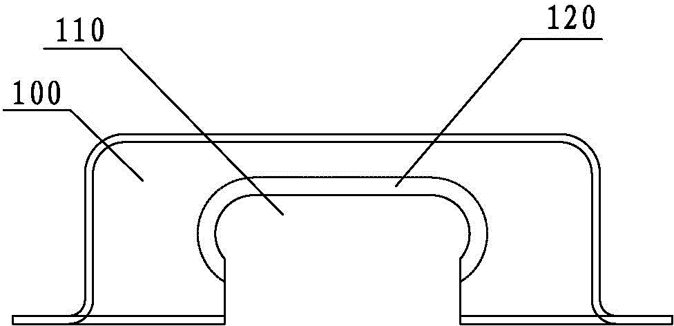
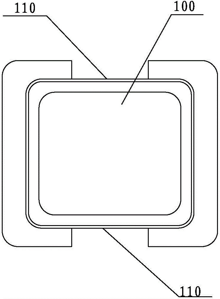
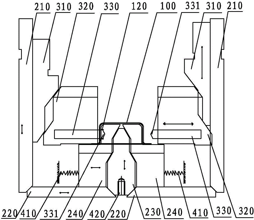
[0041] The integrated structure of double-side punching and double-side hole flanging of the double-hole shield progressive die of the present invention is as follows: Figure 1~6 shown. The double-hole shield progressive mold includes an upper mold base, an upper mold, a stripper plate, a lower mold and a lower mold base, as well as a punching guide hole station, a half-cutting station, a stretching station and a punching station for the corresponding assembly settings. Drop off the product station. The integrated structure of double-side punching and double-side hole flanging of the double-hole shield progressive mold is used in conjunction with the double-hole shield progressive mold. The double-hole shield progressive mold includes: upper mold, stripper plate and Lower mold.

[0042] The integrated structure of the double-side punching and double-side hole flanging of the double-hole shield progressive die includes the three-stage punch 210 of the inner slide block of th...

Embodiment 2

[0053] The integrated structure of double-side punching and double-side hole flanging of the double-hole shield progressive die of the present invention is as follows: image 3 , Figure 4 As shown, the main structure is the same as the above-mentioned embodiment 1, the difference is:

[0054] The side impulse force of the flanging and stripping slider 320 is transmitted by two inclined surfaces. The included angles a and b between the first punching surface 311 and the second punching surface 312 of the flanging and stripping slider punch 310 and the vertical direction are between 20 and 70 degrees. Between, the angles c and d between the first inclined surface 321 and the second inclined surface 322 of the corresponding flanging and stripping slider 320 and the vertical direction are also between 20 and 70 degrees, and the angles a and c are the same, and the angles b and d are the same. same.

[0055] Adopting this structure facilitates the transmission of the impulse bet...

Embodiment 3

[0057] The integrated structure of double-side punching and double-side hole flanging of the double-hole shield progressive die of the present invention is as follows: image 3 , Figure 4 As shown, the main structure is the same as the above-mentioned embodiment 1, the difference is:

[0058] The side impulse force of the flanging and stripping slider 320 is transmitted by two inclined surfaces. The preferred included angle between the first punching surface 311 and the second punching surface 312 of the flanging and stripping slider punch 310 and the vertical direction is between 30 and 60 degrees. . The corresponding angles c and d between the first inclined surface 321 and the second inclined surface 322 of the flanging stripping slider 320 and the vertical direction are also between 30 and 60 degrees, and the angles a and c are the same, and the angles b and d are the same.

[0059] Adopting this structure facilitates the transmission of the impulse between the flanging...


PUM


Abstract

The invention relates to the technical field of moulds and in particular relates to a double side punching-hole and double side punching-hole flange integrated structure for a double-hole shielding cover progressive mould, and the integrated structure provided by the invention comprises through holes, flanged discharging slide blocks, flanged discharging slide block limiting plates and flanged discharging slide block resetting devices respectively arranged on two sides of a discharging plate in turn, wherein slide block third-level punches in lower flanged moulds pass through the through holes; the flanged discharging slide blocks are correspondingly arranged inside the flanged discharging slide block punches; side flanged punches are arranged on the flanged discharging slide blocks; the ends, which are close to the shielding cover, of the side flanged punches are of a blade-shaped structure; side flanged punching-holes are formed on the flanged discharging slide block limiting plates; and the side flanged punching-holes are matched with the side flanged punches. Double side punching-hole and double side punching-hole flange are finished in a same process, thereby reducing a station on the mould, lowering the designing and manufacturing cost of the mould, promoting the production efficiency and reducing the defective percentage.

Description

technical field [0001] The invention relates to the technical field of moulds, in particular to an integrated structure of double-side punching and double-side hole flanging of a progressive die for a double-hole shielding cover. Background technique [0002] With the rapid development of science and technology, the application of various high-tech electronic products is becoming more and more popular, but it also brings many problems, such as the electromagnetic interference problem encountered in the use of electronic products, which not only interferes with the electronic products The normal use, but also has an adverse impact on the surrounding environment. [0003] In the prior art, one of the main means used in the design of some current devices to protect against EMI (Electromagnetic Interference, electromagnetic interference) and ESD (Electro-Static discharge, electrostatic discharge) is to use a shield to shield the source of interference Shielded to protect suscep...

Claims


Application Information

Patent Timeline
Patent Type & Authority Patents(China)
IPC IPC(8): B21D37/10B21D28/34B21D19/00
Inventor 陈松林李正中
Owner DONGGUAN DAZHONG ELECTRONICS
Learn More