
A low carbon steel hollow tube rotor structure for permanent magnet motor

A technology of permanent magnet motor and rotor structure, which is applied in the shape/style/structure of the magnetic circuit and the rotating parts of the magnetic circuit, etc., can solve the problems of large moment of inertia, complicated punching process for punching silicon steel rotor, and difficult to control flexibly, etc. achieve a reasonable structure

Inactive Publication Date: 2011-11-30
SHANDONG LIJIU SPECIAL PURPOSE ELECTROMOTOR CO LTD
View PDF5 Cites 10 Cited by
  • Summary
  • Abstract
  • Description
  • Claims
  • Application Information

AI Technical Summary

Problems solved by technology

Moreover, the punching process of punching silicon steel rotors is complicated, and it is necessary to manufacture dies and molds for laminating punches.
In particular, the moment of inertia of the rotor is large, and it is not easy to control flexibly on the servo motor

Method used


Image

  • A low carbon steel hollow tube rotor structure for permanent magnet motor
  • A low carbon steel hollow tube rotor structure for permanent magnet motor
  • A low carbon steel hollow tube rotor structure for permanent magnet motor

Examples


Embodiment Construction

[0011] The present invention will be further described below in conjunction with accompanying drawing:

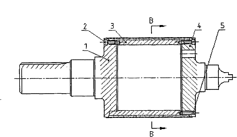
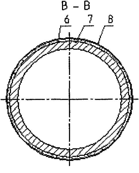
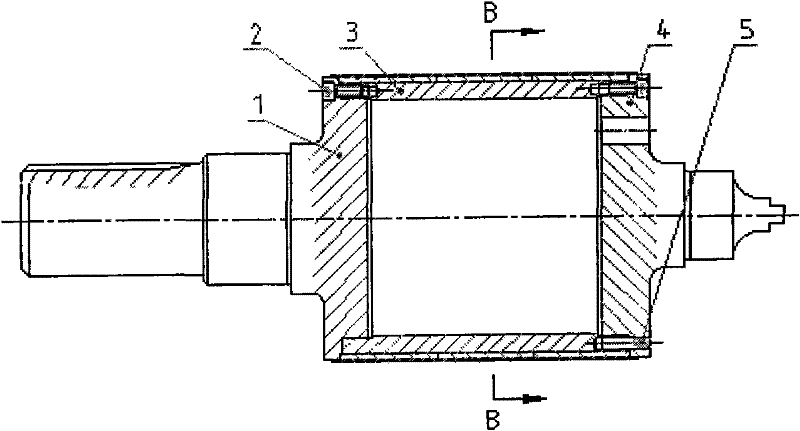
[0012] Such as figure 1 , figure 2 The shown invention relates to a low-carbon steel hollow circular tube rotor structure for a permanent magnet motor. It is provided with a rotor sleeve 3, and the two ends are installed with the shaft extension end shaft 1 and the non-shaft extension end shaft 4, which are connected by seams, and are fastened together with the rotor sleeve 3 by 12 hexagon socket head screws 2 respectively, and are connected with the rotor sleeve 3 by a cone. The pin 5 is positioned, and the outer circle of the rotor sleeve 3 is pasted with the arc-shaped magnetic steel 6 with anaerobic adhesive 7, and the inner surface of the arc is N, S, N, S... (or S, N, S, N... ) are arranged on the circumference and glued on the outer circle of the rotor sleeve 3 . Wrap carbon fiber cloth 8 outside, put glue in the oven after brushing, and dry and solidify below th...


PUM


Abstract

The invention relates to a low-carbon steel hollow circular tube rotor structure of a permanent magnet motor, which is provided with a rotor sleeve, a shaft extension end shaft, a non-shaft extension end shaft, screws, arc-shaped magnetic steel, anaerobic glue, and carbon fiber cloth. The two ends of the rotor sleeve are respectively fastened to the shaft extension end shaft and the non-shaft extension end shaft through spigots and screws. The outer circle of the rotor sleeve is pasted with arc-shaped magnetic steel with anaerobic adhesive, and the outer circle of the magnetic steel is wrapped with carbon fiber cloth. Heat to cure. When the invention is used, the arc-shaped magnetic steel is evenly distributed on the outer circle of the rotor sleeve, which solves the problem that the rotor of a multi-pole permanent magnet motor is not easy to use built-in magnetic steel, especially solves the requirement for the rotor to rotate in the servo motor Small inertia problem. The structure is reasonable, simple, convenient and practical, and is especially suitable for the rotor structure of a high-power permanent magnet synchronous torque servo motor.

Description

technical field [0001] The invention relates to a motor rotor structure, in particular to a permanent magnet motor low-carbon steel hollow circular tube rotor structure. Background technique [0002] We know that at present, the rotors of permanent magnet motors are mostly made of silicon steel sheets punched into the rotor core, and the magnetic steel is inserted inside it, that is, the built-in type. If there are too many poles of the built-in permanent magnet motor, it is difficult for the magnet steel to be distributed on the rotor punch. Moreover, the stamping process for stamping silicon steel rotors is complicated, and it is necessary to manufacture dies and molds for laminating the stampings. In particular, the moment of inertia of the rotor is large, and it is not easy to be flexibly controlled on the servo motor. Contents of the invention [0003] The technical problem to be solved by the present invention is to overcome the deficiencies of the above-mentioned ...

Claims


Application Information

Patent Timeline
Patent Type & Authority Applications(China)
IPC IPC(8): H02K1/27H02K1/28
Inventor 张成林海
Owner SHANDONG LIJIU SPECIAL PURPOSE ELECTROMOTOR CO LTD
Learn More