
Method of Data Transmission in Inductive Power Supply

An inductive power supply and data transmission technology, applied in the direction of electrical components, circuit devices, electromagnetic wave systems, etc., can solve problems such as implementation, inconvenient operation, large current passing through, and no further reduction

Active Publication Date: 2011-11-30
FU TONG TECH
View PDF6 Cites 43 Cited by
  • Summary
  • Abstract
  • Description
  • Claims
  • Application Information

AI Technical Summary

Problems solved by technology

[0006] (1) The resistance modulating device will consume power when modulating the signal. The dynamic range of the modulating signal is determined by the load resistance value. In the inductive power supply system, the primary coil needs to analyze the signal size, which will increase with the distance from the secondary coil. Therefore, when the distance increases, a larger modulation dynamic is required to analyze the data, that is, to reduce the resistance value so as to amplify the load effect in the modulation process, but this method will be limited to some extent, because the modulation load resistance is close to a short-circuit state and cannot be lowered any further
[0007] (2) In the process of resistive load modulation, it is similar to the short-circuit effect between the positive pole of the receiving end power supply and the ground, causing a momentary large current to pass through the rectifier and the voltage stabilizing device on the circuit, and the temperature rise after use will cause related components damage to
[0008] (3) Due to electrical limitations, the resistive load needs to be installed behind the rectifier, and the filter capacitor is connected across its two ends. The effect of voltage stabilization will cause the signal modulation response to be slow. In an analytic state, Requires a higher carrier frequency to operate
[0009] (4) The transmission of the signal is to feed back the signal from the secondary power receiving coil to the signal of the primary power supply coil, as a method of one-way data transmission, and it cannot be transmitted from the signal of the primary power supply coil to the method of transmitting data from the signal of the secondary power receiving coil
[0010] Therefore, how to solve the problems and deficiencies in the implementation and operation of conventional electronic devices such as charging, setting, and data transmission, and the troubles that charging and data transmission must be carried out separately, using different electronic products or equipment, is to engage in Relevant manufacturers in this industry are eager to study the direction of improvement

Method used


Image

  • Method of Data Transmission in Inductive Power Supply
  • Method of Data Transmission in Inductive Power Supply
  • Method of Data Transmission in Inductive Power Supply

Examples


Embodiment Construction

[0039] In order to achieve the above-mentioned purpose and effect, the technical means and structure adopted by the present invention, the features, functions and implementation methods of the preferred embodiments of the present invention will be described in detail as follows in order to facilitate a complete understanding.

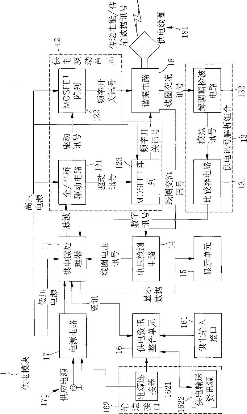
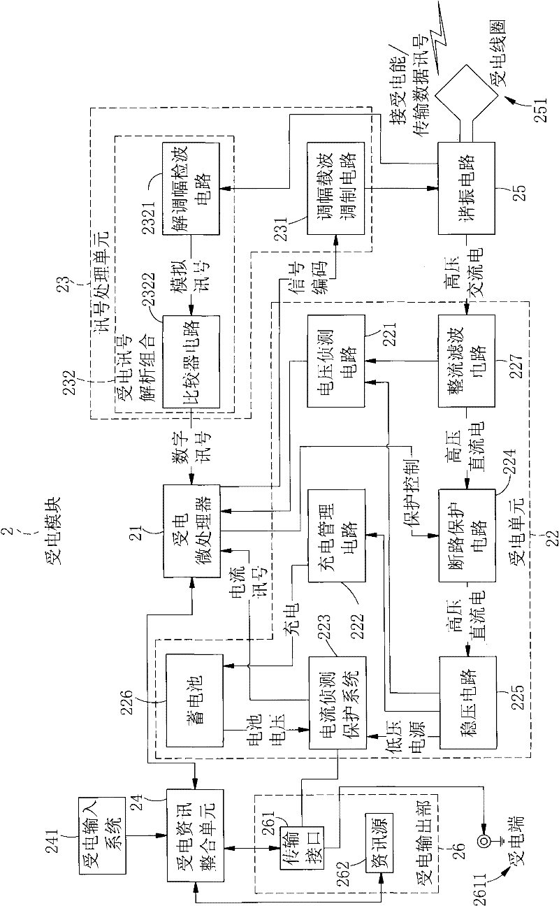
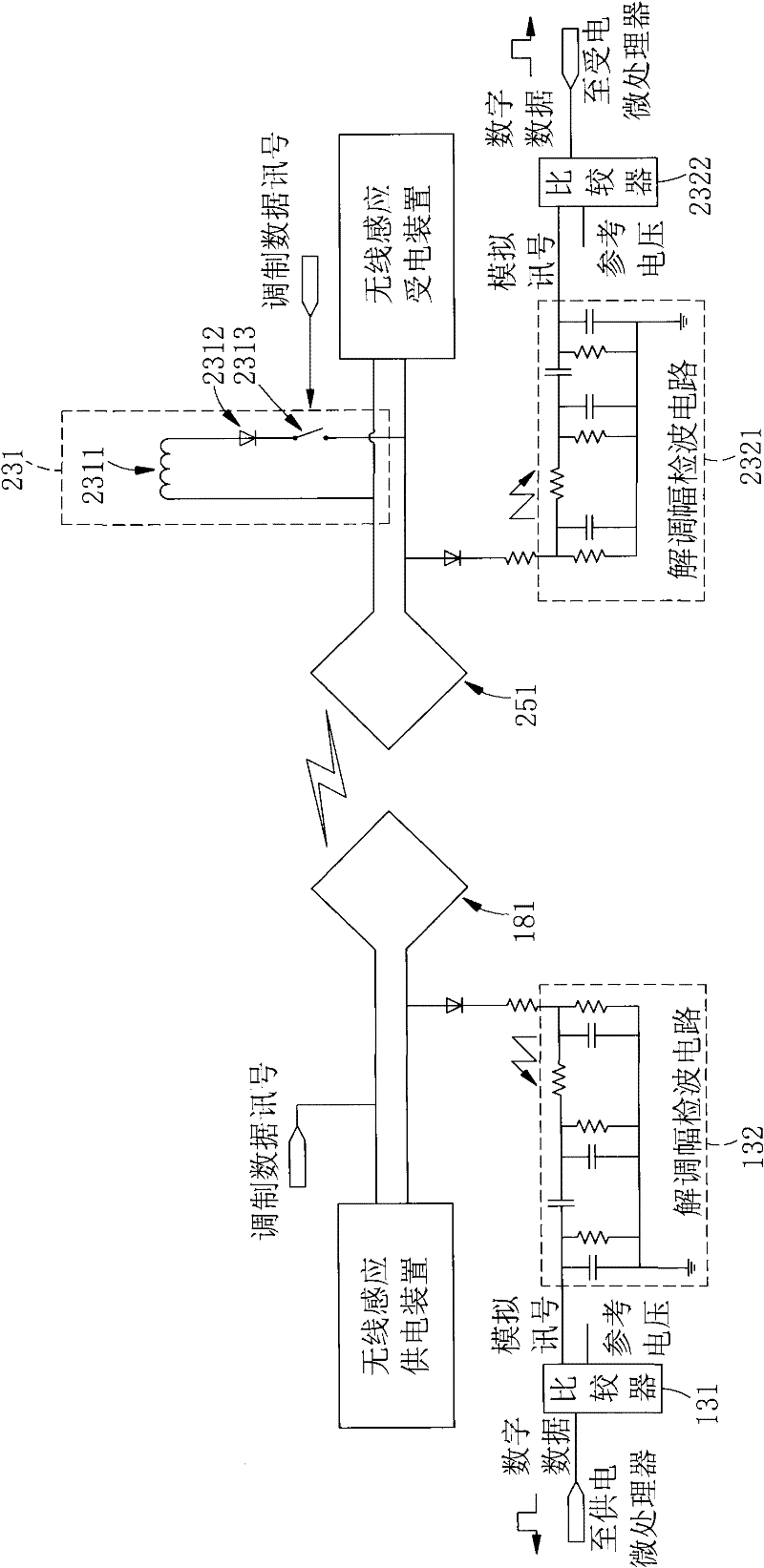
[0040] see Figures 1 to 7 Shown are respectively the block diagram of the power supply module of the present invention, the block diagram of the power receiving module, the simple circuit diagram, the step flow chart (1), the step flow chart (two), the step flow chart (three), the step flow chart (four ), it can be clearly seen from the figure that the wireless induction device of the present invention includes a power supply module 1 and a power receiving module 2, wherein:

[0041] The power supply module 1 has a power supply microprocessor 11, and related software programs such as operating procedures and control programs are provided in the power s...


PUM


Abstract

The invention discloses a data transmission method for an inductive power supply. A power supply microprocessor of a power supply module is connected with a power circuit, a power supply information integration unit, a power supply driving unit and a power supply signal resolution combination, the power supply driving unit and the power supply signal resolution combination are connected with a resonance circuit which is connected with a power supply coil. A current collection module and a current collection coil are connected with the resonance circuit. The resonance circuit is connected with a signal processing unit and a current collection unit. A current collection microprocessor is connected with the signal processing unit and a current collection information integration unit. The power supply microprocessor scans and senses a resonance point of the power supply coil, transmits a short section of power supply energy to confirm whether the current collection module feeds a signal back or not, supplies power if the current collection module feeds the signal back, checks whether the power supply information integration unit has data to be transmitted or not and whether the power supply signal resolution combination receives the signal or not, and performs signal modulation and transmission or data decoding and subsequent processing to realize power supply and data signal transmission by a wireless transmission method.

Description

technical field [0001] The present invention provides a method for data transmission in an inductive power supply. The power supply module uses the power supply coil to transmit electric energy and transmit data signals, and connects to the power receiving module through electromagnetic wave signals so that the power receiving coil receives electric energy and transmits data signals. , to achieve the purpose of synchronous charging and data transmission. Background technique [0002] The living environment has entered the digital age, and various digital products are flooding around our lives, such as digital cameras, mobile phones, music players (MP3, MP4) and other portable electronic devices, and various portable electronic devices, The products are all oriented toward light, thin, short, and small design concepts, but to achieve the purpose of being portable at any time, the first thing that must be solved is the problem of power consumption. Generally, the most common w...

Claims


Application Information

Patent Timeline
Patent Type & Authority Applications(China)
IPC IPC(8): H02J17/00H02J50/12H02J50/80
Inventor 蔡明球詹其哲
Owner FU TONG TECH
Learn More