
Constant internal pressure air spring additional air chamber with continuously changing volume and working method

An air spring and continuous volume technology, which is applied in the field of vehicle air suspension system, can solve the problems of unstable internal pressure of air spring and reduction of suspension stiffness, achieve constant internal pressure, large stiffness variation range, and realize automatic and rapid effect of change

Inactive Publication Date: 2011-11-30
JIANGSU UNIV
View PDF4 Cites 11 Cited by
  • Summary
  • Abstract
  • Description
  • Claims
  • Application Information

AI Technical Summary

Problems solved by technology

The existing structure uses the piston rod to push the piston to move to change the effective volume of the gas to achieve the purpose of changing the stiffness of the suspension; but the defect of this structure is that during the movement of the piston, due to the opening of the orifice, the additional air chamber In this way, the effective gas in the additional air chamber will reach the entire cylinder during this period, that is to say, the change in the effective volume of the additional air chamber is from the current volume to the entire additional air chamber The volume becomes the volume that needs to be adjusted. The result is: when the effective gas volume needs to decrease, the additional air chamber first suddenly increases the effective gas volume. At this initial moment, the suspension stiffness decreases instead, resulting in Air spring internal pressure instability

Method used


Image

  • Constant internal pressure air spring additional air chamber with continuously changing volume and working method
  • Constant internal pressure air spring additional air chamber with continuously changing volume and working method
  • Constant internal pressure air spring additional air chamber with continuously changing volume and working method

Examples


Embodiment Construction

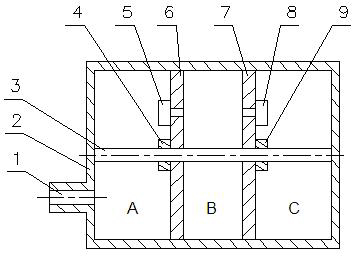
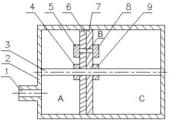
[0012] see figure 1 , the present invention has an air chamber cylinder 2, and one end of the air chamber cylinder 2 has an interface 1, and the interface 1 is connected to the air spring main air chamber, that is, the air spring main air chamber communicates with the air chamber cylinder 2 through the interface 1. Two partitions 6, 7, a double-secondary linear motor 3 and two solenoid valves 5, 8 are arranged in the cylinder body 2 of the air chamber. The first and second dividing plates 6,7 are arranged in the radial direction of the air chamber cylinder body 2, and there is a very small clearance fit between the first and second dividing plates 6,7 and the inner wall of the air chamber cylinder body 2, so that The first and second partitions 6 and 7 can move left and right in the air chamber cylinder 2 along the axial direction of the air chamber cylinder 2 . The first and second partitions 6 and 7 divide the gas chamber cylinder 2 into three chambers A, B and C, among wh...


PUM


Abstract

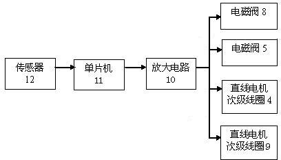
The invention discloses a constant internal pressure air spring additional air chamber which is used for air suspension systems of vehicles and of which the volume is changed continuously and an operating method. In the air chamber, two partition plates for dividing the air chamber into three cavities A, B and C in the radial direction of a cylinder body; a dual-secondary linear motor is fixedly connected to the axial directions of the two partition plates; the two secondary coils of the linear motors are connected with the two partition plates respectively; two solenoid valves are arranged at positions where the two partition plates are provided with small holes; the two solenoid valves and the secondary coils of the two linear motors are connected with an amplifying circuit; the amplifying circuit is connected with a sensor by a singlechip; the volume of the three cavities is changed by controlling the two partition plates to move right and left to increase or reduce the stiffness of a spring system, and thus, the volume of the air spring additional air chamber is changed quickly and continuously, so that an air spring has the large stiffness range, the volume of the additional air chamber is changeable but internal pressure keeps constant, and the driving stability and riding comfort of the vehicles are improved.

Description

technical field [0001] The invention belongs to the technical field of vehicle air suspension systems, and in particular relates to an additional air chamber for an air spring. Background technique [0002] The air spring in the vehicle air suspension system communicates with the additional air chamber through the airflow pipe. Therefore, the stiffness of the suspension can be controlled by controlling the effective gas volume of the additional air chamber. As the volume ratio of the additional air chamber to the main air chamber of the air spring increases, Large, the suspension stiffness decreases, and when the volume ratio increases to a certain level, the downward trend becomes very gentle. [0003] The existing additional air chamber structure is generally a volume-variable structure. A piston is arranged in the additional air chamber cylinder, and the piston divides the additional air chamber into two chambers, one of which is connected to the main air chamber of the a...

Claims


Application Information

Patent Timeline
Patent Type & Authority Applications(China)
IPC IPC(8): F16F9/02F16F9/50
Inventor 江洪金志扬肖卫军琚龙玉黄佳
Owner JIANGSU UNIV
Learn More