
High-efficiency automatic mass detonator card waist bayonet machine

A technology of waist clipping and mass firing, applied to detonators, offensive equipment, etc., can solve the problems of increasing difficulty in adjusting the waistband position, single waist or bayonet, inconvenient maintenance, etc., and reduce the production workshop and area of ​​detonators. , The effect of compact equipment and labor cost reduction

Active Publication Date: 2011-11-30
深圳金源恒业科技有限公司
View PDF4 Cites 32 Cited by
  • Summary
  • Abstract
  • Description
  • Claims
  • Application Information

AI Technical Summary

Problems solved by technology

The tightening and loosening of the bayonet and the waist of the two chucks respectively rely on the synchronous movement of the middle sleeve and the inner sleeve. The entry and extraction of the detonator are all through the mouth of the bayonet. Each machine can only complete the clamping of one detonator at a time. The work efficiency is still low, and the two sets of card valves are installed on the same card head, which increases the difficulty of adjusting the position of the card waist, and the maintenance is also inconvenient. Therefore, this technology has not been promoted in practical applications.
[0005] The inventor obtained the Chinese invention patent authorized on March 31, 2010, the patent number is "ZL 200920158188.7", which shows an "industrial detonator group firing bayonet head", which is the core of manufacturing high-efficiency detonator group firing automatic bayonet machine The mechanism can realize the bayonet of the mass detonator at the same time in one action, but this invention can only realize the single function of the waist or the bayonet

Method used


Image

  • High-efficiency automatic mass detonator card waist bayonet machine
  • High-efficiency automatic mass detonator card waist bayonet machine
  • High-efficiency automatic mass detonator card waist bayonet machine

Examples


Embodiment Construction

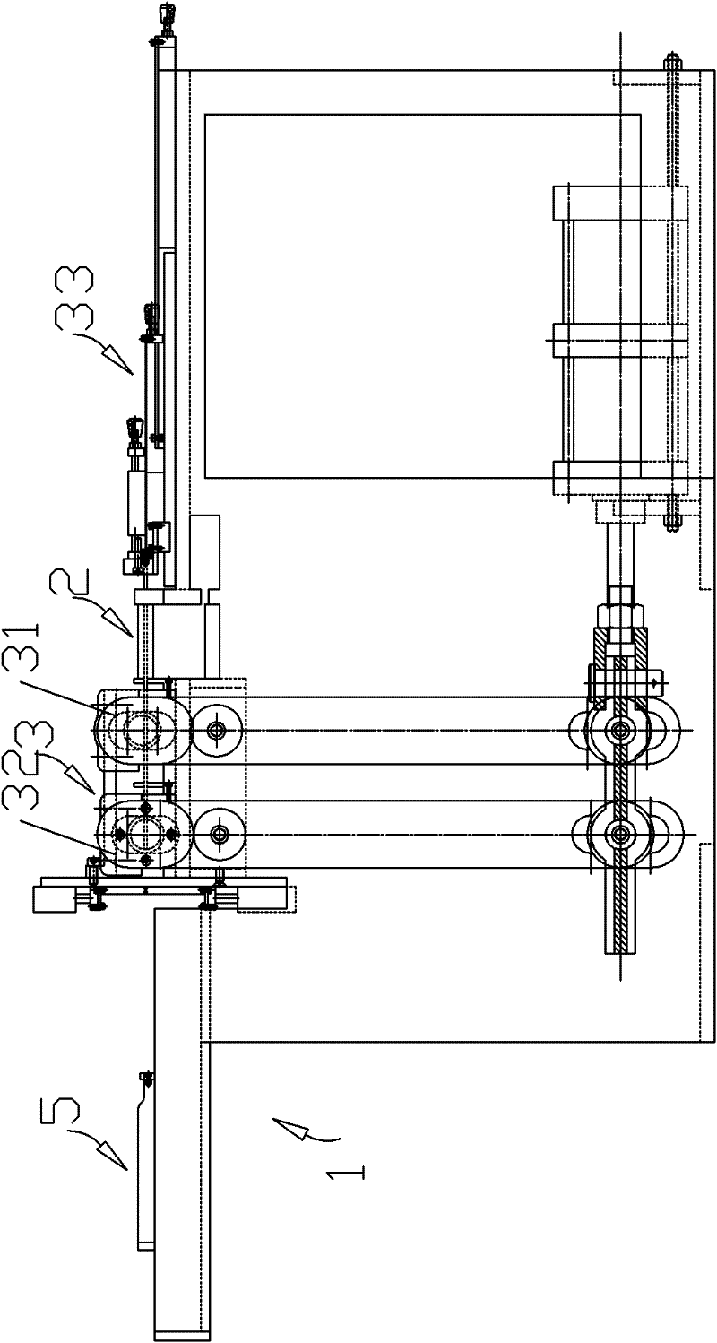
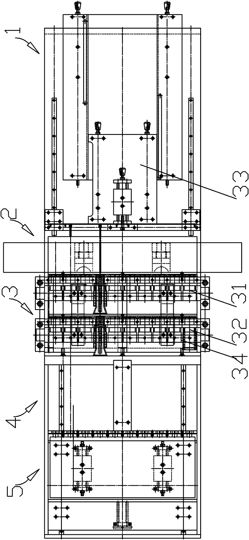
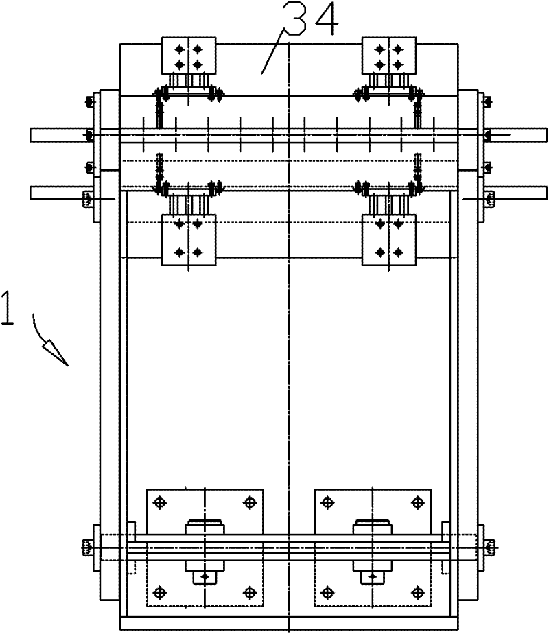
[0039] refer to figure 1 , figure 2 , image 3 As shown, a high-efficiency automatic mass detonator card waist bayonet machine is mainly composed of a frame 1, a special mold 2, a group hair card waist bayonet mechanism 3, a wire feeding mechanism 4, a payoff reel 5 and other parts and the prior art electric or Pneumatic control device constitutes; Wherein the group hair card waist bayonet mechanism 3 mainly comprises components such as waist card device 31, bayonet device 32, push tube device 33, guiding device 34.

[0040] The special-purpose mold 2, the group-issue card waist bayonet mechanism 3 and the wire feeding mechanism 4 are arranged on the platform of a frame 1, wherein the group-issue card waist bayonet mechanism 3 and the wire-feeding mechanism 4 are installed on the frame 1 The middle and rear parts; the special mold 2 is embedded between the waist device 31 and the push tube device 33 of the group-issue card waist bayonet mechanism 3, and the special mold 2 c...


PUM


Abstract

The invention relates to an efficient and automatic group-sanding latch waist-bayonet machine for detonators. The bayonet machine comprises a rack, a special mould, a play-off reel and an electric or pneumatic control device, wherein the rack is provided with the special mould, a group-sending latch waist-bayonet mechanism and a thread feeding mechanism; a group-sanding detonator latch waist and a group-sanding detonator bayonet are integrated on one machine for continuous operation, and more than ten latch waist-bayonet operations can be completed in one work process, thereby greatly improving production efficiency, saving production personnel and reducing labor cost; equipment is compact, thereby greatly reducing detonator production workshops and occupied areas; the whole assembling process is carried out automatically, and dangerous latch waist-bayonet operations are carried out in a protective armor, accidents of operating personnel injury caused by detonator explosion during latch waist and bayonet operations can be avoided, and operation is safe and reliable, thus the latch waist-bayonet machine is suitable for being used in the electric detonator or explosive detonator assembling process.

Description

technical field [0001] The invention belongs to the field of detonator production equipment, and relates to a high-efficiency automatic mass detonator card waist bayonet machine. Background technique [0002] Detonators are generally divided into electric detonators and nonel detonators. The production process of detonators is usually divided into two steps: loading and assembly. Filling is to press various pyrotechnic agents and parts into the detonator shell to make the basic detonator; the assembly line is to firmly combine the ignition element, delay element, etc. with the basic detonator. The core process is the waist and Bayonet. Among them, the bayonet is to tightly fix the delay element and the detonator shell that have been loaded in the basic detonator through the partial closure of the bayonet machine chuck; the bayonet is to close the ignition element, such as an electric starter or The plug of the detonator and the nozzle mouth of the basic detonator are close...

Claims


Application Information

Patent Timeline
IPC IPC(8): C06C7/02
Inventor 杨祖一陆全礼
Owner 深圳金源恒业科技有限公司
Learn More