Flat buckle template

A template and flat plate technology, applied in the direction of transportation, packaging, conveyors, etc., can solve the problem of inaccurate positioning, and achieve the effect of accurate positioning and easy operation

Inactive Publication Date: 2013-02-06
SHANGHAI GORO CONVEYOR EQUIP CO LTD
View PDF5 Cites 0 Cited by
  • Summary
  • Abstract
  • Description
  • Claims
  • Application Information

AI Technical Summary

Problems solved by technology

[0003] The purpose of the present invention is to provide a flat buckle template, which solves the technical problem of inaccurate positioning in the operation mode of determining the hole position and drilling on the conveyor belt in the prior art

Method used


Image

  • Flat buckle template
  • Flat buckle template
  • Flat buckle template

Examples


Embodiment Construction

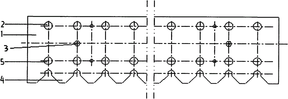
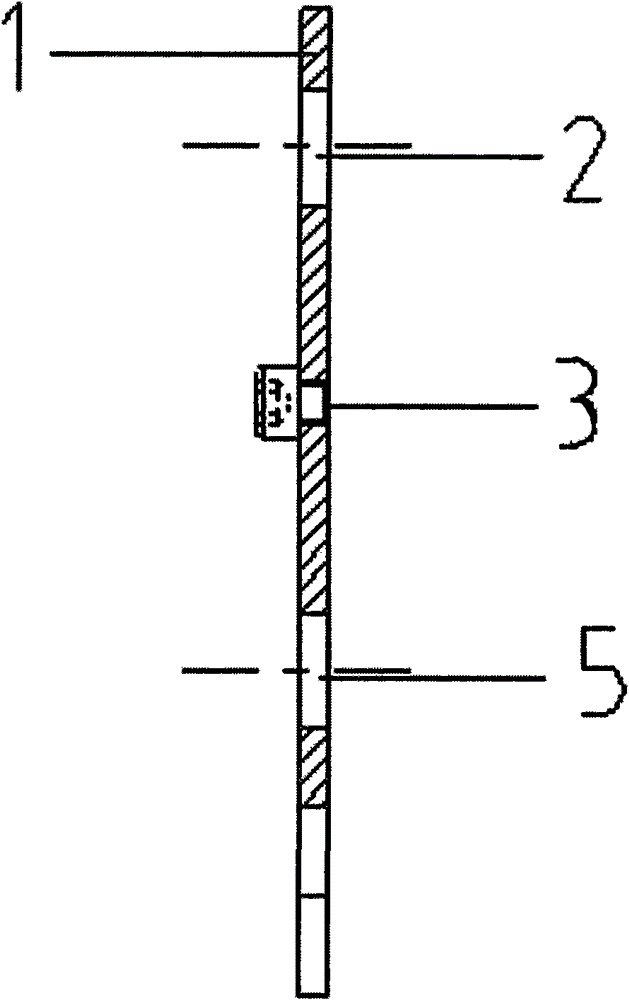
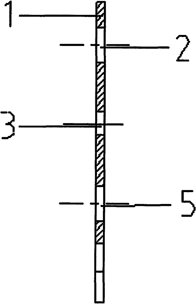
[0012] like figure 1 and figure 2 As shown, the flat plate formwork of the present invention is composed of a metal plate 1, wherein the metal plate 1 is rectangular, one side of the metal plate 1 is zigzag, and the metal plate 1 is provided with a first circular hole group and A second round hole group, the first round hole group is provided with more than two first round holes 2, and the first round holes 2 are arranged in a direction parallel to the sawtooth edge of the metal plate 1, so The second circular hole group is provided with a second circular hole 5 equal in number to the first circular hole 2, and the second circular hole 5 is arranged along a direction parallel to the sawtooth edge of the metal plate 1 and is aligned with the first circular hole. 2 in a rectangular array, the bottom of any one of the sawtooth 4 is a semicircle, and the centers of any one of the semicircles are respectively located on the longitudinal connection line between the center of the f...


PUM


Abstract

The invention discloses a flat buckle template, which is composed of a metal plate. One edge of the metal plate is saw-toothed. A first circular hole set and a second circular hole set are arranged on the metal plate. More than two first circular holes are arranged in the first circular hole set. The first circular holes are arranged in a direction parallel to the saw-toothed edge of the metal plate. Second circular holes, the number of which is the same to that of the first circular holes, are arranged in the second circular hole set. The second circular holes and the first circular holes form a rectangular array. The saw-toothed bottoms are semi-circles. Circle centres of the semi-circles are on longitudinal connection lines of circle centres of the first circular holes and circle centres of the second circular holes respectively. More than two locating pins or third circular holes are arranged on the metal plate. The locating pin or the third circular holes are arranged between thefirst circular hole set and the second circular hole set. All locating pins are vertical to the surface of the metal plate. Head faces of two conveying belts tightly press against the locating pins or the third circular holes from two sides of the locating pins or the third circular holes. The conveying belts are fixed through nails and then drilled through the first circular holes and the secondcircular holes by using a tool. The flat buckle template disclosed by the invention is precise to locate and simple and convenient to operate.

Description

technical field [0001] The invention relates to the mechanical field, in particular to a conveyor belt, in particular to a flat buckle template. Background technique [0002] The end of the conveyor belt needs to be equipped with a row of nails, so that it can be connected with the end of another conveyor belt by the pin shaft passing through the nails. When installing the fastener at the end of the conveyor belt, it is necessary to drill holes in the conveyor belt at the fastener installation position in advance. In the prior art, it is necessary to draw a line when determining the hole position on the conveyor belt, and then use a tool to drill the holes, so that the flat buckles can be arranged neatly after installation. In this way, the drilling positioning is imprecise and the operation is complicated. Contents of the invention [0003] The object of the present invention is to provide a flat buckle template, which solves the technical problem of inaccurate position...

Claims


Application Information

Patent Timeline
Patent Type & Authority Patents(China)
IPC IPC(8): B65G15/30
Inventor 吴小林
Owner SHANGHAI GORO CONVEYOR EQUIP CO LTD
Why Eureka
Try Eureka