
Remote bus alarming controller

A controller and main controller technology, applied in the direction of alarms, instruments, etc., can solve the problems of complex construction, on-site alarm information correlation and linkage, wire waste, etc., to achieve the effect of convenient construction and wire saving

Inactive Publication Date: 2011-11-23
SHANGHAI LENTONE COMM TECH
View PDF9 Cites 4 Cited by
  • Summary
  • Abstract
  • Description
  • Claims
  • Application Information

AI Technical Summary

Problems solved by technology

[0003] At present, the traditional remote alarm system uses telephone and local area network access to realize remote alarm. For the access of alarm signals, multi-wire wiring is mostly used, directly wiring from multiple alarm detectors to the alarm controller, which has complex construction and waste of wires. Features
[0004] Chinese utility model patent specification CN 200720171761 (authorized announcement date: September 10, 2008) discloses a "bus system networked alarm system", but this method is only suitable for large-scale application occasions, and there is no on-site image alarm information. Unable to meet the needs of remote alarm
[0005] Chinese utility model patent specification CN200720063771 (authorized announcement date: January 16, 2008) discloses an "indoor remote video monitoring and alarm system", but the system must have a place with LAN access before it can be used
[0006] Chinese invention patent specification CN200710145598 (authorized announcement date: April 21, 2010) discloses a "a remote alarm video monitoring method", but this method is not associated and linked with on-site alarm information, and must be monitored 24 hours a day. Judgment and alarm, save monitoring fatigue
[0007] Chinese invention patent specification CN200920189382 (authorized announcement date: June 09, 2010) discloses a "remote anti-theft alarm", but this method can only realize the telephone alarm function, and cannot realize the on-site image alarm information

Method used


Image

  • Remote bus alarming controller
  • Remote bus alarming controller
  • Remote bus alarming controller

Examples


Embodiment Construction

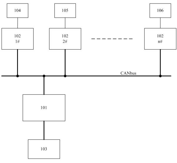
[0020] A preferred embodiment of the present invention is described in detail as follows in conjunction with accompanying drawing: figure 1 As shown, the remote bus alarm controller includes a main controller 101, multiple node controllers 102, multiple alarm detectors 104, 105, 106, and a GSM MMS module 103.

[0021] The main controller 101 is connected with the node controller 102 by the CANbus bus, the main controller 101 is connected with the GSM MMS module 103 by the RS232 bus, and the node controller 102 is connected with the alarm detectors 104, 105, 106.

[0022] Alarm detectors can be divided into infrared detectors 104, smoke detectors 105, door and window magnets 106, and the like.

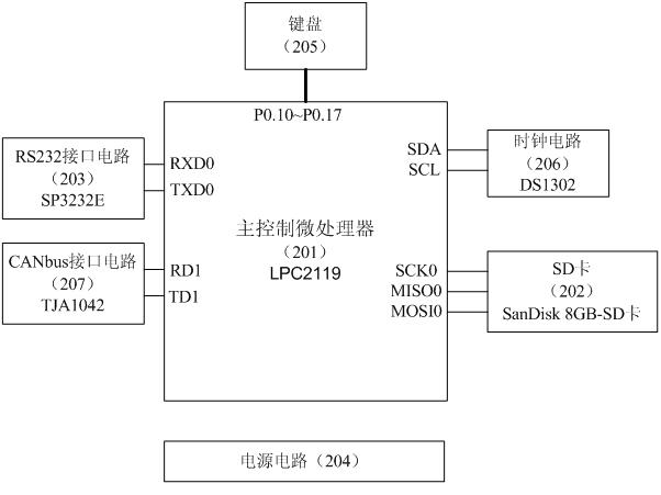
[0023] Such as figure 2 As shown, main control microprocessor 201, clock circuit 206, RS232 interface circuit 203, SD card 202, CANbus interface circuit 207, power control circuit 204, keyboard 205, etc. are built in main controller 101.

[0024] The main control microprocessor 201 a...


PUM


Abstract

The invention discloses a remote bus alarming controller. The remote bus alarming controller comprises a master controller, a plurality of node controllers, a plurality of alarming detectors and a GSM (Global System for Mobile Communications) multimedia message module, wherein the master controller is connected with each node controller through a CAN (Control Area Network) bus, the master controller is connected with the GSM multimedia message module through an RS232 bus, and the node controllers are connected with the alarming detectors. The remote bus alarming controller can be used in any place where remote alarming is necessary, and uses the bus technology inside to implement the online state routing inspection of the plurality of node controllers and the real-time quick transmission of control information and alarming information. The remote bus alarming controller can implement multi-node remote image alarming and can be controlled by remote short messages, and simultaneously, the remote bus alarming controller is high in system reliability, extremely low in false alarm rate, convenient for installment construction and can save cost on wires, so that the remote bus alarming controller is suitable for any place where remote alarming is needed to be implemented.

Description

technical field [0001] The invention relates to the field of security protection, in particular to a remote alarm controller. Background technique [0002] In unattended substations, warehouses, military bases and other places, remote alarm and anti-intrusion alarm systems are required. [0003] At present, the traditional remote alarm system uses telephone and local area network access to realize remote alarm. Most of the alarm signal access adopts multi-wire wiring mode, directly wiring from multiple alarm detectors to the alarm controller, which has complex construction and waste of wire materials. Features. [0004] Chinese utility model patent specification CN 200720171761 (authorized announcement date: September 10, 2008) discloses a "bus-based networked alarm system", but this method is only suitable for large-scale application occasions, and there is no on-site image alarm information. Can't adapt to the needs of remote alarm. [0005] Chinese utility model patent...

Claims


Application Information

Patent Timeline
IPC IPC(8): G08B25/04
Inventor 唐智杰罗均
Owner SHANGHAI LENTONE COMM TECH
Learn More