
Stamping die

A technology of stamping dies and punches, which is applied in the field of molds, and can solve problems such as unstable clamping of punches, clamping heads, and short service life of clamping dies.

Inactive Publication Date: 2011-11-23
SICHUAN DELI RAILWAY TECH
View PDF5 Cites 0 Cited by
  • Summary
  • Abstract
  • Description
  • Claims
  • Application Information

AI Technical Summary

Problems solved by technology

[0002] At present, most of the punches used in the factory have problems such as unstable punch clamping, easy breakage, and stuck head; moreover, after punching the blank, the blank is not easy to take out, and the service life of the clamping die is short.
[0003] Subsequently, devices such as rotary punch fixing devices, upper and lower die blank fixing devices, thickened inserts and other devices appeared. However, these structures often require greater stress when stamping the blank. If The thread is fixed, and the reaction force it bears during stamping will make the thread slip, and the punch will swing accordingly, which will affect the processing accuracy.
The upper and lower opening and closing pressing plates are used to achieve the effect of clamping the blank. When opening the pressing plate, due to the gravity of the pressing plate itself, it is necessary to add manual external force to open the pressing plate, which also increases the labor intensity of the workers virtually.
The upper and lower clamping molds are arranged, so the lower clamping mold must be reinforced. As mentioned in the above scheme, "the diameter of the middle section is larger than the diameter of the two end sections", and the guide plate is set. This technical scheme increases the operation. Difficulty, and the whole equipment has complex process defects
[0004] Therefore, none of these structures really solve the above-mentioned technical deficiencies

Method used


Image

  • Stamping die
  • Stamping die
  • Stamping die

Examples


Embodiment 1

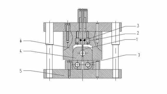
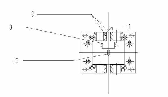
[0024] A stamping die, comprising a punch body, a fixed sleeve and a fixed pin, two movable molds arranged in opposite directions in the longitudinal direction, an insert, a lower mold base, two upper fixed blocks, a spring, and two rotating shafts, the fixed sleeve is provided with a concave One end of the punch body is embedded in the groove, and two symmetrical first arc-shaped grooves are opened on the punch body embedded in the groove, and on the side of the groove corresponding to the arc-shaped groove The wall is provided with a concave second arc-shaped groove, the first arc-shaped groove on the punch body and the second arc-shaped groove on the wall of the groove form a through hole, and the fixed pin cooperates with the through hole to make The punch body is fixed in the groove, the two upper fixed blocks are fixedly connected to both sides of the fixed sleeve, one end of the two movable molds is respectively connected to the lower mold seat through the rotating shaft...

Embodiment 2

[0026] A stamping die, comprising a punch body, a fixed sleeve and a fixed pin, two movable molds arranged in opposite directions in the longitudinal direction, an insert, a lower mold base, two upper fixed blocks, a spring, and two rotating shafts, the fixed sleeve is provided with a concave One end of the punch body is embedded in the groove, and two symmetrical first arc-shaped grooves are opened on the punch body embedded in the groove, and on the side of the groove corresponding to the arc-shaped groove The wall is provided with a concave second arc-shaped groove, the first arc-shaped groove on the punch body and the second arc-shaped groove on the wall of the groove form a through hole, and the fixed pin cooperates with the through hole to make The punch body is fixed in the groove, the two upper fixed blocks are fixedly connected to both sides of the fixed sleeve, one end of the two movable molds is respectively connected to the lower mold seat through the rotating shaft...

Embodiment 3

[0028] A stamping die, comprising a punch body, a fixed sleeve and a fixed pin, two movable molds arranged in opposite directions in the longitudinal direction, an insert, a lower mold base, two upper fixed blocks, a spring, and two rotating shafts, the fixed sleeve is provided with a concave One end of the punch body is embedded in the groove, and two symmetrical first arc-shaped grooves are opened on the punch body embedded in the groove, and on the side of the groove corresponding to the arc-shaped groove The wall is provided with a concave second arc-shaped groove, the first arc-shaped groove on the punch body and the second arc-shaped groove on the wall of the groove form a through hole, and the fixed pin cooperates with the through hole to make The punch body is fixed in the groove, the two upper fixed blocks are fixedly connected to both sides of the fixed sleeve, one end of the two movable molds is respectively connected to the lower mold seat through the rotating shaft...


PUM

PropertyMeasurementUnit
Temperature resistanceaaaaaaaaaa

Abstract

The invention discloses a stamping die, belonging to the field of dies, and comprising a punch body, a fixed jacket, a fixed pin, two movable dies arranged longitudinally and oppositely, an insert, a lower die holder, two upper fixed blocks, a spring and two spindles, wherein the punch is embedded in the groove of the fixed jacket; and when the punch is pressed down, the two movable dies are closed by the fixed blocks on the fixed jacket in the pressing-down process, thus clamping a blank. By adopting the stamping die, the punch is fixed firmly and is convenient to assemble and dissemble, theblank is clamped firmly and is easy to take out, the service life of the movable dies is long, the machining precision is high and the labor intensity is reduced.

Description

technical field [0001] The invention discloses a stamping die, which belongs to the field of dies, and in particular belongs to a clamping die which needs to punch a heated billet. Background technique [0002] At present, most of the punches used in the factory have problems such as unstable punch clamping, easy breakage, and stuck head; moreover, after punching the blank, the blank is not easy to take out, and the service life of the clamping die is short. [0003] Subsequently, devices such as rotary punch fixing devices, upper and lower clamping die blank fixing devices, thickened inserts and other devices appeared. However, these structures often require greater stress when stamping the blank. If If the thread is fixed, the reaction force it bears during stamping will make the thread slip, and the punch will swing accordingly, which will affect the processing accuracy. The upper and lower opening and closing press plates are used to achieve the effect of clamping the b...

Claims


Application Information

Patent Timeline
IPC IPC(8): B21D28/34B21D28/36
Inventor 陈开德
Owner SICHUAN DELI RAILWAY TECH
Learn More