Visible light compound eye positioner

A visible light, locator technology, applied in photometry, instruments, scientific instruments, etc., can solve the problems of increasing the field of view and response speed of positioning, poor anti-interference ability, slow response speed, etc. Response speed and precision, simple structure effect

Inactive Publication Date: 2013-08-14
NORTHWESTERN POLYTECHNICAL UNIV
View PDF8 Cites 0 Cited by
  • Summary
  • Abstract
  • Description
  • Claims
  • Application Information

AI Technical Summary

Problems solved by technology

[0003] In order to overcome the disadvantages of the prior art positioning, such as small field of view, slow system response speed, and poor anti-interference ability of the system, the present invention provides a visible light compound eye locator, which uses an optical compound eye structure and a circuit system to collect visible light and process it , the system can not only increase the field of view and response speed of positioning, but also has small size, light weight and low energy consumption, and can be easily applied to the tracking and positioning of various solar panel arrays

Method used


Image

  • Visible light compound eye positioner
  • Visible light compound eye positioner
  • Visible light compound eye positioner

Examples


Embodiment Construction

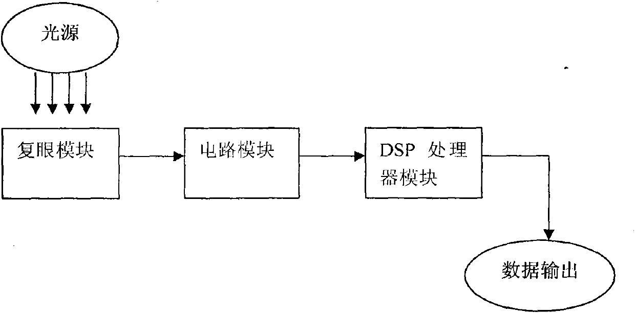
[0012] exist figure 1 Among them, the compound eye module is connected with the circuit module, and the circuit module is connected with the DSP processor module.

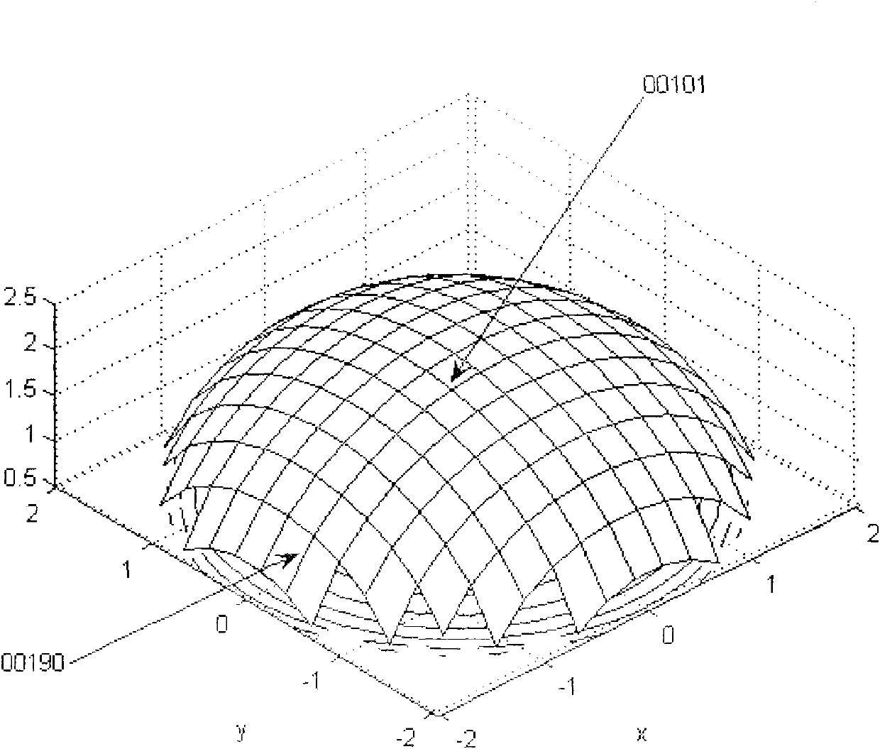
[0013] exist figure 2 Among them, each monocular is numbered with five decimal numbers according to its corresponding space pitch angle and azimuth angle. The number change interval is 00101-36090.

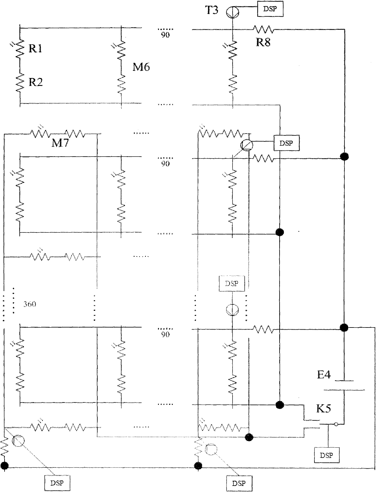
[0014] exist image 3 In the shown embodiment, the photoresistor R1 and the fixed value resistor R2 are connected in series to form a column resistance module M6 and a row resistance module M7. 90 column resistance modules M6 are connected in parallel to form a parallel circuit, and 360 parallel circuits form a row circuit array. 360 row resistance modules M7 are connected in parallel to form a column parallel circuit, and 90 column parallel circuits form a column circuit array. The row circuit array and the column circuit array are independent of each other. The row circuit array and the column circuit array are...


PUM


Abstract

The invention discloses a visible light compound eye positioner. According to the invention, hemisphere face of a semispherical compound eye is divided into 32400 small grids; each grid is provided with a simple eye which comprises a convex lens and a cylindrical fiber connected with the bottom of the convex lens; each simple eye is connected with two photoresistor modules which are a column resistor module and a row resistor module in adjacent position; a circuit module is formed by the photoresistor modules and is externally connected with a DSP processor through a voltage sensor and powered by the DSP processor. According to the invention, visible light is effectively collected and processed; responding speed and precision in positioning are enhanced; the positioner has a small volume,light weight, simple structure and low energy consumption, and is convenient to assemble and apply.

Description

technical field [0001] The invention relates to a visible light positioning system, which is suitable for positioning applications of visible light such as solar photoelectric and photothermal ray tracing positioning. Background technique [0002] At present, solar tracking has been widely used in various solar energy application systems. The tracking and positioning technology for sunlight is developing rapidly. The general tracking and positioning of sunlight to adjust the orientation of solar panels is made up of photosensitive or heat-sensitive components and some control systems. Composition, through the difference in the sensing amount of sunlight at different angles by the photosensitive or heat-sensitive components arranged at different positions on the solar panel, the data is transmitted to the control system to correct the orientation of the solar panel. Since the sunlight optical path directly contacts the sensing components without going through an intermediate ...

Claims


Application Information

Patent Timeline
Patent Type & Authority Patents(China)
IPC IPC(8): G01C1/00G01J1/04G01J1/42
Inventor 赵平徐冠青王伟张灵培徐立
Owner NORTHWESTERN POLYTECHNICAL UNIV
Why Eureka
Try Eureka