
Device for pulling out cylinder head fuel injector sleeve

A fuel injector and cylinder head technology, which is applied in the field of engine maintenance tooling, can solve problems such as mixing, fuel injector cover removal, and increased maintenance workload, and achieve the effects of reducing labor intensity, simple structure, and simplified maintenance processes

Inactive Publication Date: 2011-11-02
BRITISH JOINT VENTURE PERKINS ENGINES TIANJIN
View PDF5 Cites 3 Cited by
  • Summary
  • Abstract
  • Description
  • Claims
  • Application Information

AI Technical Summary

Problems solved by technology

During the use of the engine, if the O-ring fails, it will cause the coolant to mix with the diesel, and the consequences of the failure are very serious
It is necessary to replace a new O-ring during fault maintenance. First, unscrew the thread of the fuel injector sleeve. It is difficult to remove the fuel injector sleeve without removing the engine cylinder head, but if the cylinder head is removed, Maintenance workload will be greatly increased

Method used


Image

  • Device for pulling out cylinder head fuel injector sleeve
  • Device for pulling out cylinder head fuel injector sleeve
  • Device for pulling out cylinder head fuel injector sleeve

Examples


Embodiment Construction

[0012] In order to further understand the content of the invention, features and effects of the present invention, the following embodiments are exemplified and described in detail with the accompanying drawings as follows:

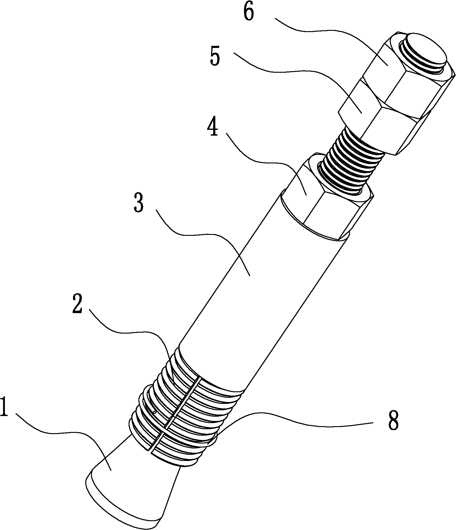
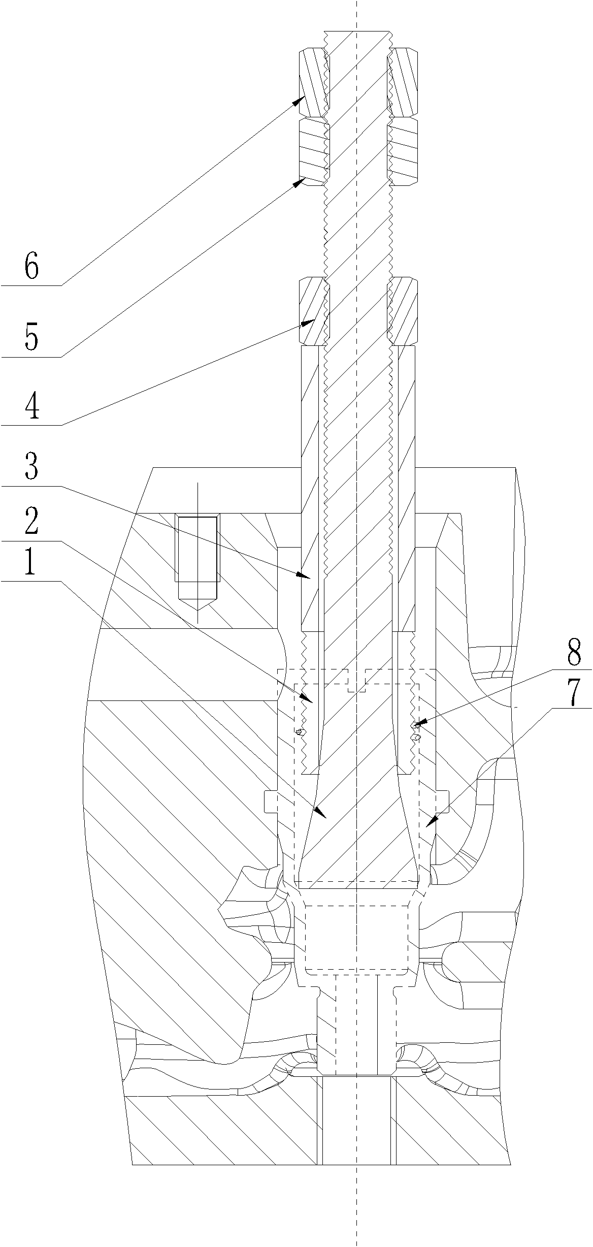
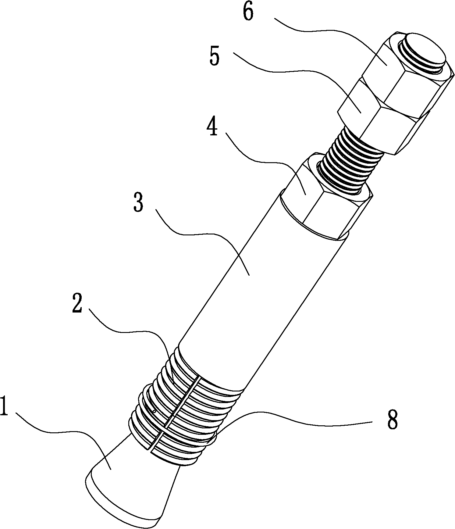
[0013] see figure 1 and figure 2 , a cylinder head injector sleeve pulling device, the pulling device mainly includes a screw 1 with a thread at one end and a conical structure at the other end, the upper part of the tapered end of the screw 1 is sleeved with an expanding sleeve 2, and the expanding sleeve is The upper end screw 1 of 2 is sleeved with a spacer 3, which can slide freely between the spacer 3 and the screw 1. The upper screw 1 of the spacer 3 is equipped with a locking nut 4, and the threaded end of the screw 1 is equipped with a lock nut 4. Two lock nuts (5, 6) are installed. When in use, clamp the lock nut 6 at the upper end with an external tool to prevent the lock nut 4 from rotating synchronously with the screw 1.

[0014] In order ...


PUM


Abstract

The invention relates to a device for pulling out a cylinder head fuel injector sleeve. The device is characterized by mainly comprising a threaded rod, one end of the threaded rod is a threaded end and the other end of the threaded rod is of a taper structure; an expanding sleeve is sleeved on an upper part of the taper end of the threaded rod; a spacer sleeve is sleeved on the threaded rod at the upper end of the expanding sleeve; the spacer sleeve can freely slide on the threaded rod; a lock nut is arranged on the threaded rod above the separating sleeve; and two lock nuts are arranged at the threaded end part of the threaded rod. In the invention, an expanding type principle is adopted and is implemented in such a ways that: by adjusting the lock nuts, the spacer sleeve tightly presses the expanding sleeve, an external surface of the expanding sleeve tightly presses an inner wall of the fuel injector sleeve, then a certain friction force exists between the expanding sleeve and the fuel injector sleeve; and after the expanding sleeve tightly presses the fuel injector sleeve, the device provided by the invention is pulled out so as to pull out the fuel injector sleeve by depending on the friction force between the expanding sleeve and the fuel injector sleeve, the lock nuts are unlocked after the fuel injector sleeve is pulled out, and the dismounting work can be completed just by dismounting the fuel injector sleeve. Thus, the device provided by the invention has a simple structure, and is convenient to use, the technology for maintaining an O-shaped ring of a cylinder head is simplified, the time for maintenance work is shortened, meanwhile, the labor intensity of operators is also lowered.

Description

technical field [0001] The invention belongs to the field of engine maintenance tooling, in particular to a pull-out device for disassembling an engine cylinder head fuel injector sleeve. Background technique [0002] When designing the cylinder head of a diesel engine, it is a common design to assemble the injector mounting sleeve in the cylinder head assembly for direct fuel injection technology. Usually, the O-ring is used to isolate the coolant and diesel in the cylinder head. For the detailed structure, see Figure 1 . During the use of the engine, if the O-ring fails, it will cause the coolant to mix with the diesel, and the consequences of the failure are very serious. A new O-ring needs to be replaced during fault maintenance. First, unscrew the injector sleeve thread. If the engine cylinder head is not removed, it is difficult to remove the injector sleeve, but if the cylinder head is removed, the The maintenance workload will be greatly increased. SUMMARY OF TH...

Claims


Application Information

Patent Timeline
Patent Type & Authority Applications(China)
IPC IPC(8): B25B27/00
Inventor 刘勇李方成肖婵马艳
Owner BRITISH JOINT VENTURE PERKINS ENGINES TIANJIN
Learn More