
Lacrimal passage drainage system

A lacrimal duct and drainage tube technology, applied in the field of medical devices, can solve problems such as blockage, and achieve the effects of avoiding pain, low rejection, and good stability

Active Publication Date: 2013-06-12
项楠 +1
View PDF7 Cites 0 Cited by
  • Summary
  • Abstract
  • Description
  • Claims
  • Application Information

AI Technical Summary

Problems solved by technology

Lacrimal duct stents placed on the lacrimal duct for a long time are prone to granulomas and blockage again, especially for refractory lacrimal duct diseases that cannot be re-canalized due to various reasons such as trauma, tumors, and congenital lacrimal duct deformities, which cannot be cured clinically. Solve problems that cause great suffering to patients

Method used


Image

  • Lacrimal passage drainage system
  • Lacrimal passage drainage system
  • Lacrimal passage drainage system

Examples


Embodiment 1

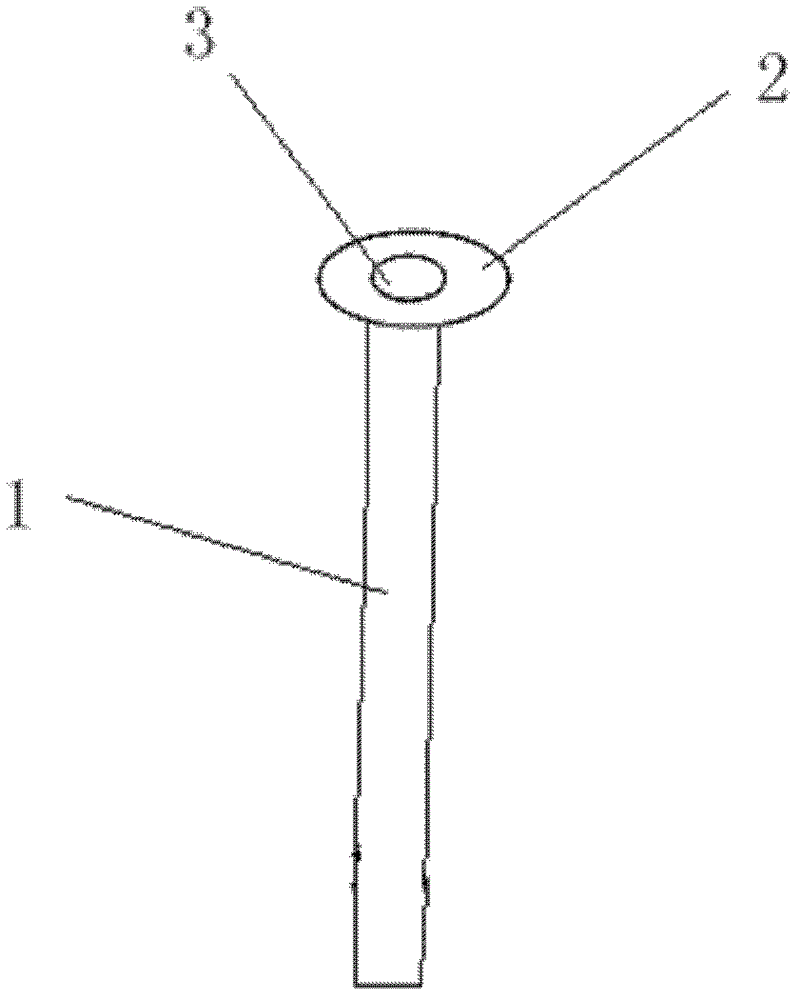
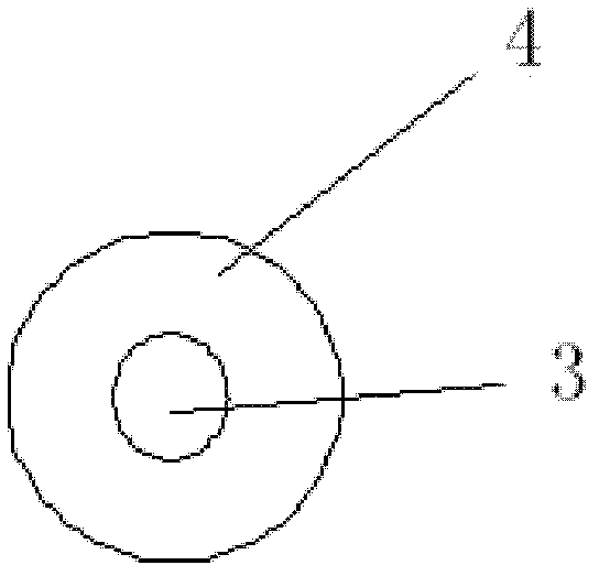
[0045] Such as Figure 1-2 The shown lacrimal duct drainage system of the present invention includes a hollow lacrimal duct drainage tube 1 and a tube that is located on the top of the lacrimal duct drainage tube 1 and is connected to the lacrimal duct drainage tube 1 and has the same inner diameter as the lacrimal duct drainage tube 1 . The pressure cap 2 of the central circular hole 3.

[0046] Since the specific data such as the width of the nasal cavity, the depth of the conjunctival sac, and the curvature of the nasolacrimal duct are not the same for patients of different ages or even different individuals, the length of the lacrimal drainage tube of the present invention needs to be determined according to the above parameters. To adjust, the general length of lacrimal drainage tube is 20 ~ 60mm. The outer diameter of the lacrimal duct drainage tube is determined according to the anatomical structure of the human body, preferably 0.8-4.0 mm. The inner diameter of the l...

Embodiment 2

[0059] Such as Figure 4-5 The difference between the shown example and Example 1 lies in that the connection mode between the pressing cap and the lacrimal duct drainage tube is different. In this example, the pressure cap and the lacrimal duct drainage tube are not integrally formed, but detachable. In this example, the hole wall of the central circular hole 3 extends downwards to form a continuous cylindrical extension 6, and the top of the lacrimal duct drainage tube 1 is inserted into the extension section 6 from below the pressure cap 2, and the outer tube wall of the lacrimal duct drainage tube 1 and The inner walls of the extension section 6 are in close contact, so that the two are detachably fixedly connected.

[0060] In the present invention, the extension section can also be inserted into the upper section of the lacrimal drainage tube from above the lacrimal duct drainage tube, so that the inner tube wall of the lacrimal duct drainage tube is in close contact wi...

Embodiment 3

[0063] The difference between this example and embodiment 2 is that the shape of the brim piece of the pressure cap 2 is different, and in this example, the brim piece is as follows Figure 6-7 The shown elliptical sheet is also detachably tightly connected with the lacrimal duct drainage tube through the round hole in its center.


PUM


Abstract

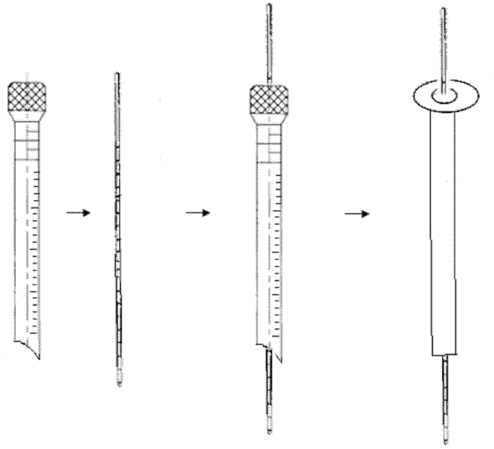
The invention provides a lacrimal passage drainage system. The lacrimal passage drainage system is characterized by comprising a hollow lacrimal passage drainage tube and a press cap which is positioned at the top of the lacrimal passage drainage tube, is connected with the lacrimal passage drainage tube and is provided with a central round hole having the same inner diameter as the inner diameter of the lacrimal passage drainage tube; the press cap is provided with a cap edge piece extending outwards from the edge of the central round hole; and the inner wall of the lacrimal passage drainagetube is smooth. The lacrimal passage drainage system provided by the invention has simple structure and good stability, can be implanted into the nasal cavity of a human body for long-term use without rejection reaction, and can work together with the corresponding components as required to achieving the functions of cleaning, dredging, draining and redundant tissue removing.

Description

technical field [0001] The invention relates to a medical appliance, in particular to a lacrimal duct drainage system for treating lacrimal duct obstruction. Background technique [0002] At present, the commonly used methods for the treatment of lacrimal duct obstruction are nasal dacryocystor anastomosis, lacrimal duct intubation, and lacrimal duct stent surgery. Nasal dacryocystostomy is more traumatic, and the recurrence rate after lacrimal cannulation is higher. Lacrimal duct stents placed on the lacrimal duct for a long time are prone to granulomas and blockage again, especially for refractory lacrimal duct diseases that cannot be re-canalized due to various reasons such as trauma, tumors, and congenital lacrimal duct deformities, which cannot be cured clinically. The problem solved caused great pain to the patient. Contents of the invention [0003] The present invention is completed to solve the deficiencies in the prior art. The purpose of the present invention ...

Claims


Application Information

Patent Timeline
Patent Type & Authority Patents(China)
IPC IPC(8): A61F9/007
Inventor 项楠于刚
Owner 项楠
Learn More