


Quick Research
Generate reliable direction feasibility study reports for your R&D in just a few steps.

Technical Q&A
Discover and master advanced knowledge NOW. Basics, ideas, possibilities, all at once.

Find Solutions
As an expert in R&D theories, this can generate solutions to your technical problems instantly.

Evaluate Feasibility
Analyze your overall solution with one click, know your potential R&D risks in advance.

Monitor Landscape
Get weekly tech updates, stay abreast of the latest tech innovations and key insights.
High-strength member structure for auto bodies
A component structure, high-strength technology, applied in the superstructure, substructure, vehicle components and other directions, can solve problems such as damage to air conditioning equipment
- Summary
- Abstract
- Description
- Claims
- Application Information
AI Technical Summary
Problems solved by technology
Method used
Image

Examples
Embodiment 1
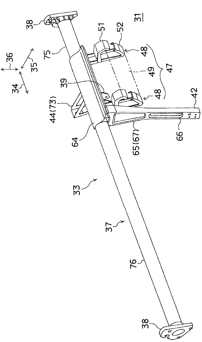
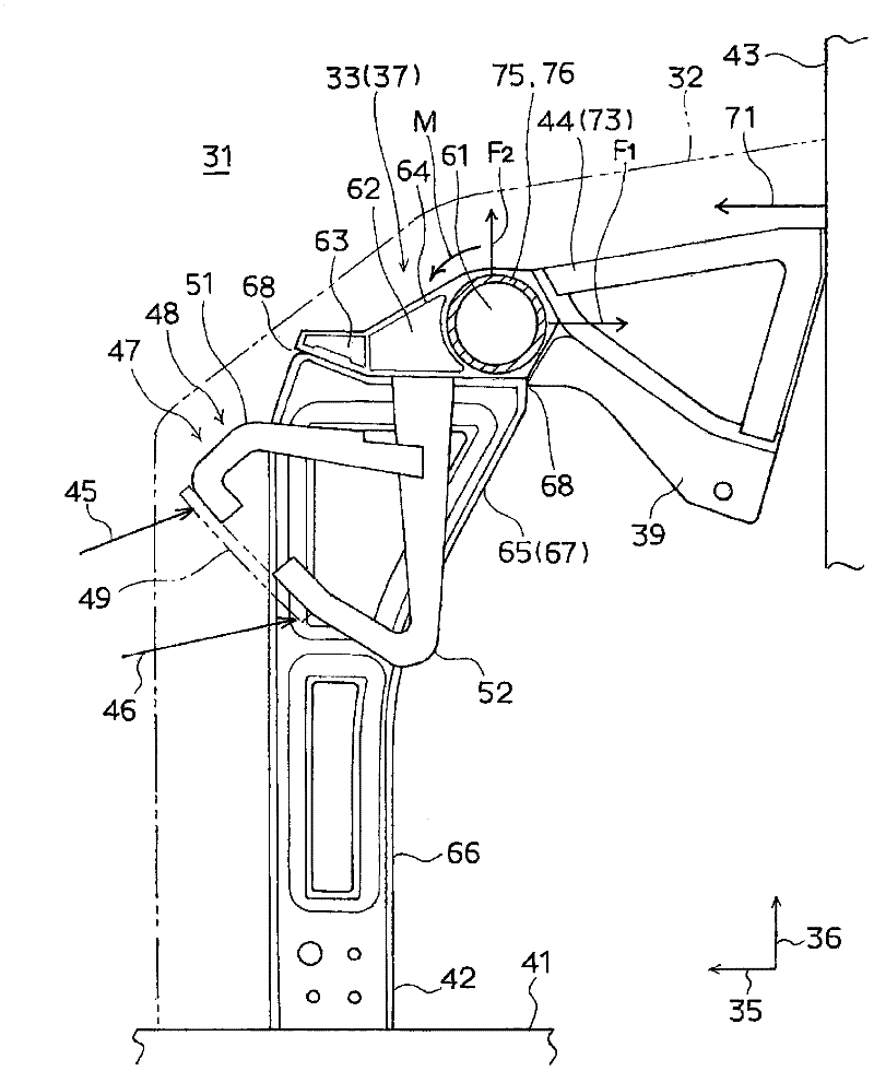
[0141] exist figure 1 , figure 2 The structure diagram of this embodiment is shown in .
[0142] First, the basic structure will be described.
[0143] In vehicles such as automobiles, a resin instrument panel 32 (refer to figure 2 ). A metal high-strength member 33 for a vehicle body is provided inside the instrument panel 32 .
[0144] Here, reference numeral 34 is a vehicle width direction, 35 is a vehicle front-rear direction, and 36 is an up-down direction. Such a high-strength vehicle body member 33 includes a high-strength vehicle body member main body 37 extending substantially in the vehicle width direction 34 .
[0145] The vehicle body high-strength member main body 37 provided at the front in the compartment 31 has side brackets 38 attached to left and right vehicle body panels (side panels, not shown) at both ends thereof. The side bracket 38 is made of metal and fixed to the high-strength vehicle body member body 37 by welding.
[0146] Furthermore, thi...
Embodiment 2
[0193] The purpose of this embodiment is mainly to improve the overall performance of the strut bracket, and to secure the deformation stroke even if the input direction of the emergency input load deviates.
[0194] Hereinafter, embodiments for realizing the present invention will be described with reference to the accompanying drawings.
[0195] In addition, the following embodiments are closely related to the above-mentioned background technology and the problems to be solved by the invention. Therefore, when necessary, the described contents can be borrowed from each other, or can also be borrowed from each other with necessary modifications.
[0196] Figure 7 ~ Figure 21 This example and its modifications are shown.
[0197] First, the basic mechanism will be described.
[0198] In the figure, reference numeral 241 is a vehicle width direction, 242 is a vehicle front-rear direction, and 243 is an up-down direction.
[0199] Such as Figure 7 , Figure 8 As shown, in...
Embodiment 3
[0240] The purpose of this embodiment is mainly to improve the strength and rigidity of the main body of the high-strength component for the vehicle body when the emergency input load acts.
[0241] Embodiments for realizing the present invention will be described below in conjunction with the accompanying drawings.
PUM
 Abstract
Description
Claims
Application Information
 - R&D Engineer
- R&D Manager
- IP Professional
- Industry Leading Data Capabilities
- Powerful AI technology
- Patent DNA Extraction
Browse by: Latest US Patents, China's latest patents, Technical Efficacy Thesaurus, Application Domain, Technology Topic, Popular Technical Reports.
© 2024 PatSnap. All rights reserved.Legal|Privacy policy|Modern Slavery Act Transparency Statement|Sitemap|About US| Contact US: help@patsnap.com