Degassing device for liquid-filled chambers with rotating components

A technology of exhaust device and rotating component, which is applied to components of pumping device for elastic fluid, liquid fuel engine, pump element, etc. gas effect

Active Publication Date: 2011-10-12
KSB AG
View PDF7 Cites 0 Cited by
  • Summary
  • Abstract
  • Description
  • Claims
  • Application Information

AI Technical Summary

Problems solved by technology

Such a solution requires a very large construction volume and is expensive

Method used


Image

  • Degassing device for liquid-filled chambers with rotating components
  • Degassing device for liquid-filled chambers with rotating components
  • Degassing device for liquid-filled chambers with rotating components

Examples


Embodiment Construction

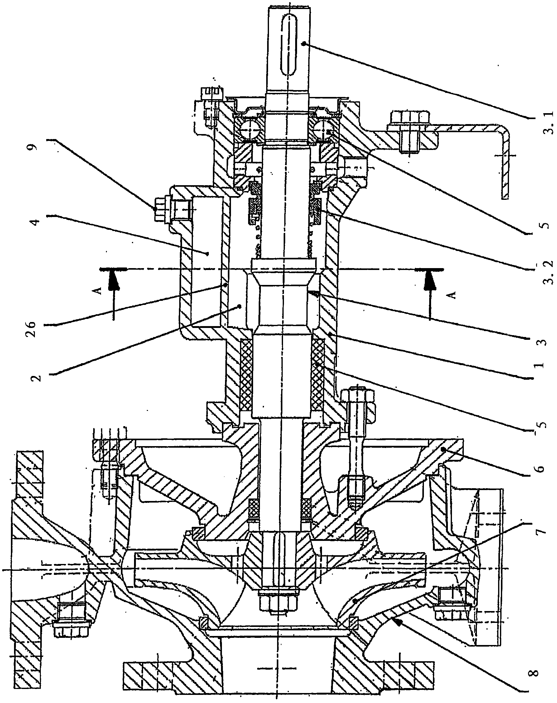
[0022] exist figure 1 The exhaust device for a centrifugal pump is shown in the example of a drive shaft. The exhaust device is arranged in a housing 1 and has a chamber 2 with a rotating component 3 arranged therein. This is a shaft 3.1 and a shaft seal 3.2 mounted thereon, which is formed as part of a slip ring seal. In this sectional depiction can be seen the exhaust chamber 4 mounted on the upper part of the shaft 3.1, delimited from the chamber 2 by the element 6 explained below. The shaft 3 . 1 held in the bearing 5 passes through the pump cover 6 and carries the impeller 8 of the centrifugal pump 8 . The liquid located in the centrifugal pump flows along the axis 3.1 into the chamber 2 of the exhaust device.

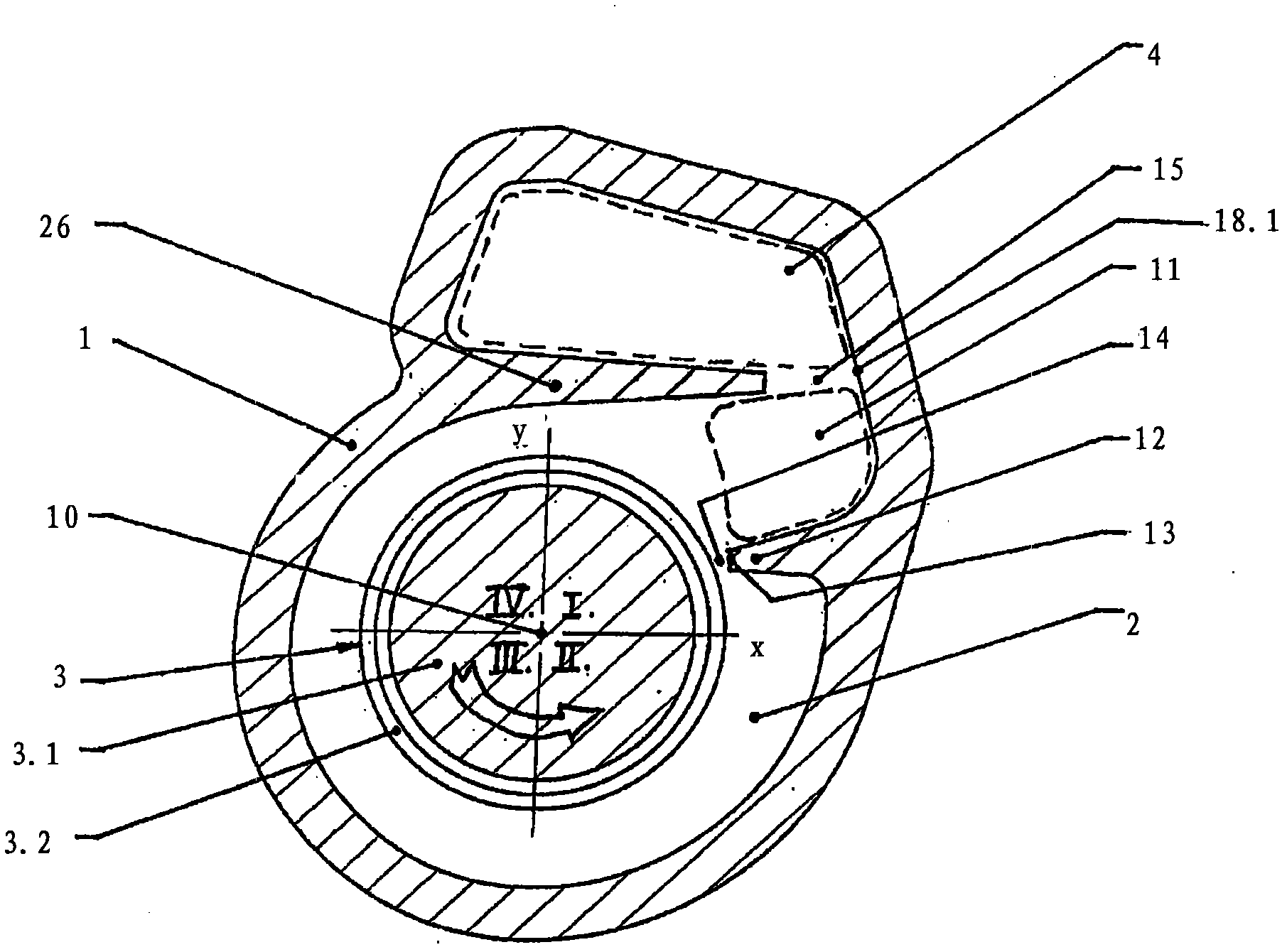
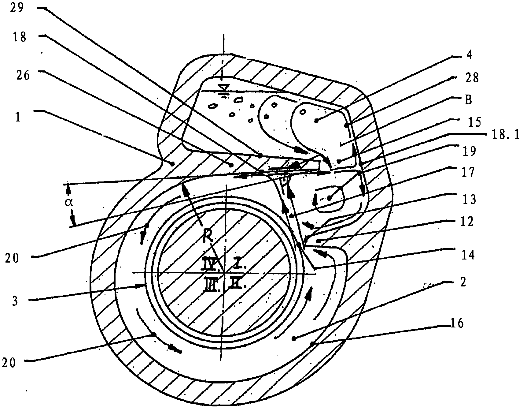
[0023] If there is no exhaust and there is gas in the chamber 2 or inside the liquid, the gas will collect directly on the rotating member 3 due to the difference in density and under the influence of centrifugal force. In contrast, the liquid rotates around t...


PUM


Abstract

The present invention relates to a degassing device which is composed of a housing with a chamber with a rotating component arranged therein, in particular a shaft, a bearing arrangement and / or a shaft seal. At least one rib, which extends with a free rib end up to the rotating component so as to form an axially parallel gap, is attached in the chamber. Positioned downstream of the gap is a degassing chamber for a liquid. A jet splitter wall surface (18) for splitting up a gap jet (17) is arranged in the chamber (2) at a distance from an acceleration gap (14) and opposite the acceleration gap (14). At a lateral distance from a gap projection (B) onto the jet splitter wall surface (18), said jet splitter wall surface (18) is provided with one or more connecting openings (15) to the degassing chamber.

Description

technical field [0001] The invention relates to an exhaust device comprising a housing with a chamber with a rotating component arranged therein, in particular a shaft, a bearing arrangement and / or a shaft seal, wherein at least one utilization-free rib is mounted in the chamber The end reaches the rib of the rotating member under forming an axis-parallel slot, and the vent chamber for the liquid is arranged after the slot. Background technique [0002] For centrifugal pumps conveying hot liquids having at least one shaft channel through the pump housing, EP 0 327 549 B1 discloses a venting device for a pump shaft with slip ring seals. To this end, its slide ring seal is surrounded by the interior of a chamber with a concentric ring wall arranged at a distance therefrom, which has radial ribs standing outwards and inwards. The chambers separated by the ring wall are connected to each other by holes. Stabilization of the liquid circulation with this vent should be achieved ...

Claims


Application Information

Patent Timeline
IPC IPC(8): F04D29/10F04D29/12F16J15/34
CPCF04D29/106F04D29/126
Inventor L·乌尔班S·普拉格尔
Owner KSB AG
Why Eureka
Try Eureka