Coil winding device

A winding device and coil technology, applied in electromechanical devices, manufacturing motor generators, electrical components, etc., can solve the problems of messy and uneven coils and low efficiency of winding devices

Inactive Publication Date: 2011-10-05
CHIZHOUSHI HONGGANG SCI & TECH ELECTRONICS CO LTD
View PDF0 Cites 0 Cited by
  • Summary
  • Abstract
  • Description
  • Claims
  • Application Information

AI Technical Summary

Problems solved by technology

[0003] The purpose of the present invention is to provide a coil winding device to solve the problem of low efficiency of the prior art winding device and prone to messy and uneven coils

Method used


Image

  • Coil winding device
  • Coil winding device

Examples


Embodiment Construction

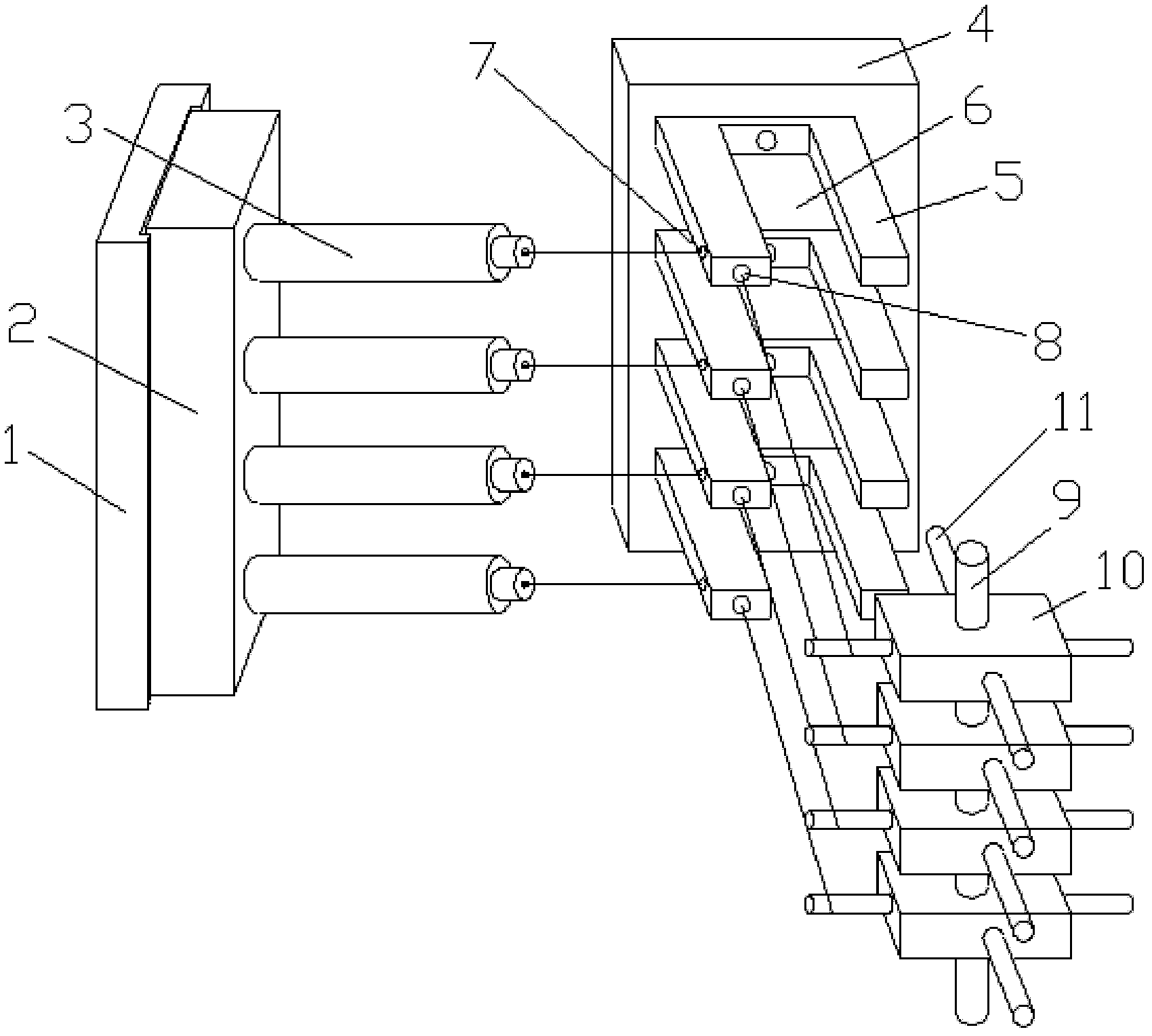
[0010] A coil winding device, including a wire feeding mechanism, a tensioning mechanism, and a wire winding mechanism arranged on a platform, the wire feeding mechanism includes a wire feeding seat 1, and is vertically slidably installed on the vertical seat surface of the wire feeding seat 1 The wire feeding box 2 on the top, the wire feeding box 2 is provided with a plurality of horizontal wire feeding heads 3 perpendicular to the vertical seat surface of the wire feeding seat 1;

[0011] The tensioning mechanism includes a vertical tensioning seat 4, and a plurality of tensioning cards 5 are installed on the vertical seat surface of the tensioning seat 4. The tensioning cards 5 are frame-shaped structures, and the tensioning cards 5 pass through the frame edge of the rear end. Rotate and install on the vertical seat surface of the tensioning seat 4, and the front frame edge of the tensioning card 5 is disconnected to form a bayonet 6, from the side frame edge of the tension...


PUM


Abstract

The invention discloses a coil winding device, which comprises a wire feeding mechanism, a tensioning mechanism and a wire winding mechanism. The wire feeding mechanism comprises a wire feeding seat, a wire feeding box and wire feeding heads on the wire feeding box. The tensioning mechanism comprises a tensioning seat and a plurality of tensioning clamps. Wire feeding through holes are reserved from lateral rims of the tensioning clamps to the front end faces of the front rims, connected with the lateral rims, of the tensioning clamps. The wire winding mechanism comprises a plurality of rectangular seats arranged on a vertical rotating shaft. Wire winding rods are connected to the sidewalls of the rectangular seats. The coil winding device is simply structured and easy to implement, greatly improves the winding efficiency, and can effectively solve the problem of disorder and unevenness of a coil in winding by the tensioning mechanism.

Description

technical field [0001] The invention relates to a wire winding device, in particular to a coil winding device. Background technique [0002] The full name of micro motor is micro special motor, which is often used in control systems to realize the detection, calculation, amplification, execution or conversion of electromechanical signals or energy, or for transmission of mechanical loads, and can also be used as AC and DC power supplies for equipment. The motor contains a plurality of coils, so the coils need to be wound during the production of the motor, but the winding efficiency of the existing winding device is low, and the coils are prone to messy and uneven problems after winding. Contents of the invention [0003] The object of the present invention is to provide a coil winding device to solve the problems of low efficiency and prone to messy and uneven coils of the existing winding device. [0004] In order to achieve the above object, the technical scheme adopte...

Claims


Application Information

Patent Timeline
IPC IPC(8): H02K15/04
Inventor 翟云飞
Owner CHIZHOUSHI HONGGANG SCI & TECH ELECTRONICS CO LTD
Why Eureka
Try Eureka