
Vehicle wheel

A wheel and rim technology, applied in the direction of wheels, spoked wheels, rims, etc., can solve problems such as cost increase, and achieve the effect of suppressing stress concentration, ensuring rigidity, and improving rigidity

Inactive Publication Date: 2011-10-05
HONDA MOTOR CO LTD
View PDF7 Cites 5 Cited by
  • Summary
  • Abstract
  • Description
  • Claims
  • Application Information

AI Technical Summary

Problems solved by technology

Although a method of changing the material to an aluminum alloy, magnesium alloy, etc. with a lighter specific gravity is also conceivable, the cost increases

Method used


Image

  • Vehicle wheel
  • Vehicle wheel
  • Vehicle wheel

Examples


Embodiment Construction

[0061] Embodiments of the present invention will be described below with reference to the drawings.

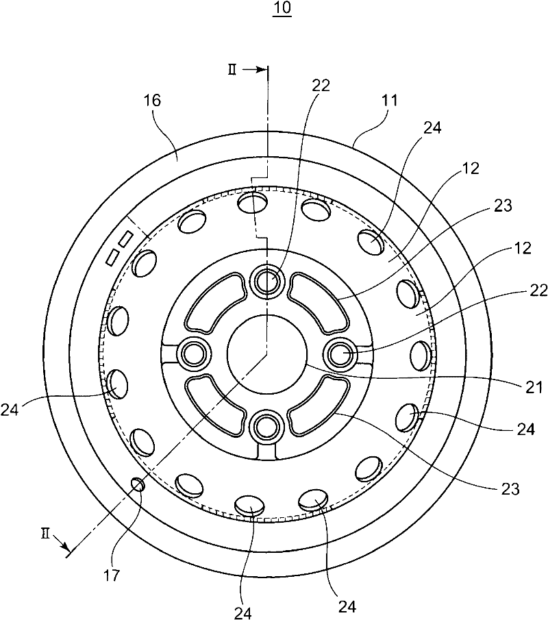
[0062] figure 1 It is an external view of the wheel of the embodiment.

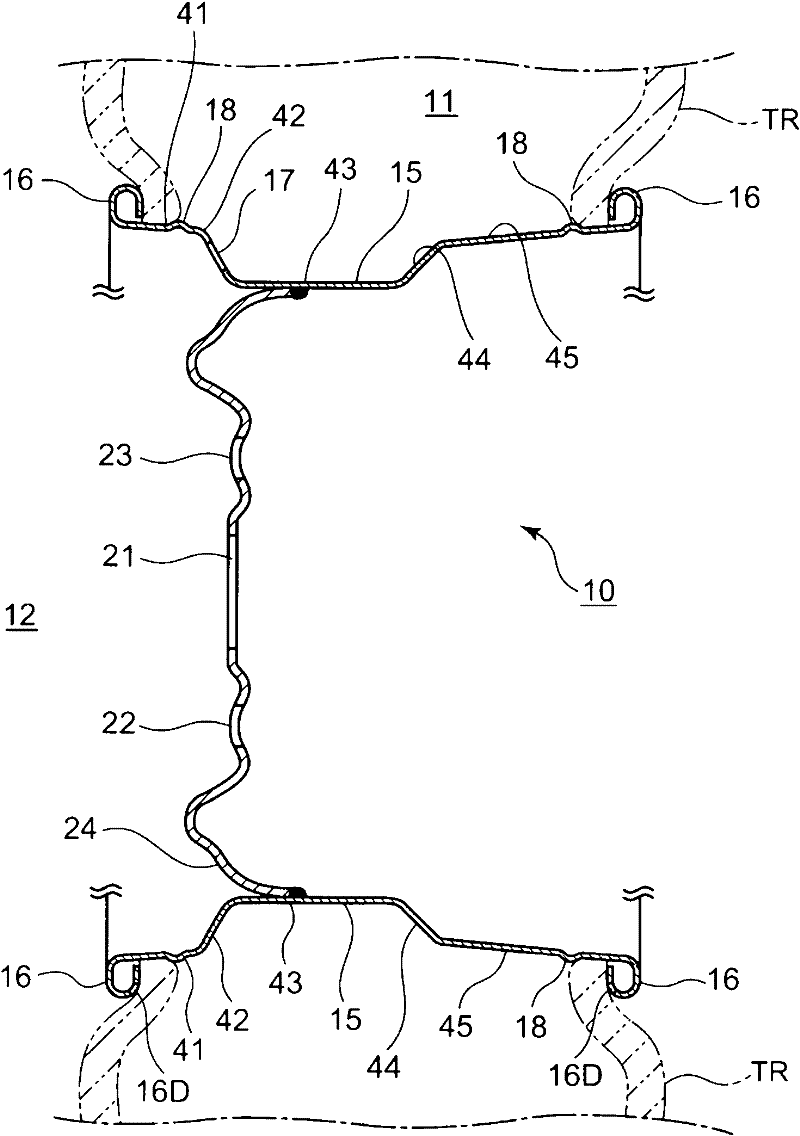
[0063] in addition, figure 2 for along figure 1 Sectional end view of the wheel II-II line.

[0064] The wheel 10 generally includes a substantially cylindrical rim portion 11 and a substantially disk-shaped disc portion 12 joined to the rim portion 11 .

[0065] rim part 11 such as figure 2 As shown, there is a rim body portion (recessed portion) 15 formed by shrinking the peripheral surface of the rim portion 11, and rims formed along the peripheral surface of the rim portion 11 at both ends of the rim portion 11, respectively. The flange portion 16, the valve hole 17 through which a valve (not shown) is inserted when the tire TR is mounted, and the peak portion 18 for making it difficult to disengage when the air pressure of the tire TR drops.

[0066] The wheel disc portion 12 has a hub hole 2...


PUM

PropertyMeasurementUnit
thicknessaaaaaaaaaa

Abstract

Disclosed is a vehicle wheel which is excellent in appearance quality, is light, and has stiffness. The vehicle wheel (10) has a rim section (11) which has a substantially cylindrical shape and into which a tire (TR) is fit, and a disk section (12) having a substantially disk shape and bonded to the inside of the rim section (11), wherein the rim section (11) includes a rim body part (15) and a rim flange part (16), the rim body part (15) is formed such that the thickness of a part to which the disk section is bonded is thicker than the thicknesses of the other parts, and the rim flange part (16) is formed by bending both thin end parts of the rim body part (15) into a hollow shape.

Description

technical field [0001] The present invention relates to wheels, and more particularly to two-piece wheels having a rim portion and a disc portion. Background technique [0002] The rim portion and the disc portion constituting the wheel require strong rigidity in view of their usage characteristics, and in order to ensure the rigidity, each must have a thick thickness, which increases the weight. A method of changing the material to an aluminum alloy, a magnesium alloy, or the like having a light specific gravity is also conceivable, but the cost increases. In response to this situation, conventionally, a so-called spinning method has been proposed in order to suppress the wall thickness of the rim portion using steel materials. In this spinning method, while rotating a cylindrical workpiece, a roller is pushed against the workpiece from the outer peripheral surface toward the inside, thereby shrinking the workpiece to form a rim portion (see Patent Document 1). . [0003...

Claims


Application Information

Patent Timeline
Patent Type & Authority Applications(China)
IPC IPC(8): B60B3/00B60B21/00B21D22/00
CPCB21D22/16B21D53/30B21D22/18B60B21/023B21D19/12B60B3/044B60B21/104Y10T29/49513
Inventor 内田裕之松林干政半田秋男
Owner HONDA MOTOR CO LTD
Learn More