
Automatic gain control circuit of audio power amplifier

A technology of automatic gain control and audio power, which is applied in the direction of gain control, amplification control, and improvement of control circuits by reducing distortion, and can solve problems such as harmonic distortion and output clipping

Inactive Publication Date: 2011-09-28
SHANGHAI SANDHILL MICROELECTRONICS
View PDF4 Cites 25 Cited by
  • Summary
  • Abstract
  • Description
  • Claims
  • Application Information

AI Technical Summary

Problems solved by technology

[0004] The technical problem to be solved by the present invention is to overcome the defects in the above-mentioned prior art, that is, when a large audio signal is input, the output will be clipped after modulation and demodulation, resulting in harmonic distortion, and to provide an audio Power Amplifier Automatic Gain Control Circuit

Method used


Image

  • Automatic gain control circuit of audio power amplifier
  • Automatic gain control circuit of audio power amplifier
  • Automatic gain control circuit of audio power amplifier

Examples


Embodiment Construction

[0017] The present invention will be further described below in conjunction with the embodiments and the accompanying drawings.

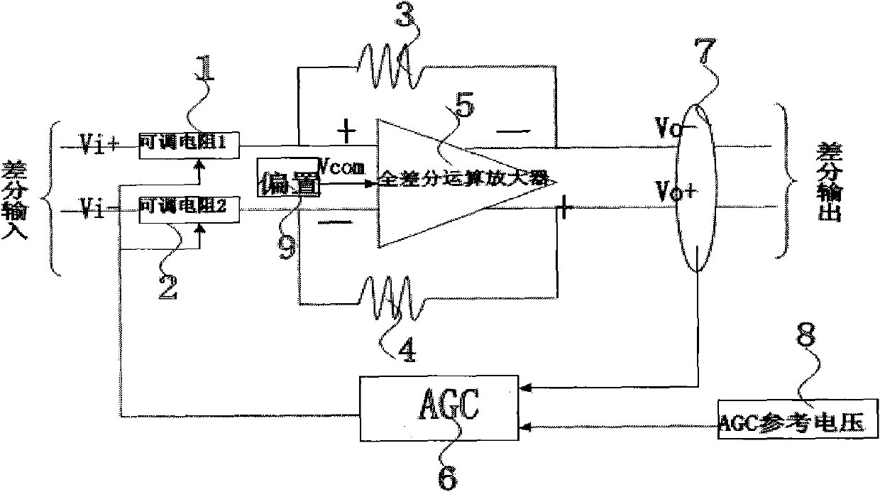
[0018] refer to figure 2 , the present invention includes a fully differential operational amplifier 5, the same and inverting input terminals of the fully differential operational amplifier 5 are respectively provided with an adjustable resistor 1 and an adjustable resistor 2. A feedback resistor 3 is provided between the non-inverting input terminal and the output terminal, a feedback resistor 4 is provided between the inverting input terminal and the output terminal, a bias circuit 9 is connected to the fully differential operational amplifier 5, and an automatic gain control The input terminal of the circuit (AGC) 6 is connected to the audio output terminal 7 of the fully differential operational amplifier 5, the reference voltage circuit 8 is connected to the automatic gain control circuit 6, and the output terminal of the automatic gain contr...


PUM


Abstract

The invention discloses an automatic gain control circuit of an audio power amplifier, which comprises a fully differential operational amplifier and an automatic gain control circuit, wherein the in-phase and anti-phase input ends of the amplifier are provided with divider resistors respectively; feedback resistors are arranged between the in-phase input end and an output end as well as between the in-phase input end and the output end respectively; a biasing circuit is connected the fully differential operational amplifier; the input end of the control circuit is connected with the output end of the fully differential operational amplifier; a reference voltage circuit is connected with the control circuit; and the output end of the control circuit is connected with an adjustable resistor at the input end of the fully differential operational amplifier. In the invention, an output signal is compared with a reference voltage to obtain a digital signal, and the digital signal is used for controlling the front resistance value of the input end of the amplifier, so that a fixed gain can be kept for amplifying an audio signal during inputting of a small signal, closed-loop gain in the circuit is reduced during inputting of a large audio signal, and high linearity and low harmonic distortion of an output audio signal are ensured.

Description

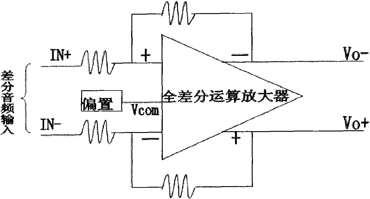
【Technical field】 [0001] The invention relates to an audio frequency power amplifier in the field of large-scale analog integrated circuit design, in particular to an audio frequency power amplifier automatic gain control circuit. 【Background technique】 [0002] figure 1 It is a circuit structure of a traditional power audio amplifier in the prior art. In this circuit structure, the audio signal is amplified by a fully differential operational amplifier. The output of the audio signal changes with the input. When a large audio signal is input (Vi+ and Vi- are relatively large), the audio input signal is amplified by a fully differential operational amplifier, and the output Vo- and Vo+ are also relatively large, resulting in The output peak value of the audio signal is relatively large, and if the signal is modulated and demodulated, the demodulated signal will produce top distortion, resulting in a large amount of harmonic distortion and poor sound quality. [0003] In th...

Claims


Application Information

Patent Timeline
IPC IPC(8): H03G3/20H03G1/04
Inventor 肖国庆蒋锦茂
Owner SHANGHAI SANDHILL MICROELECTRONICS
Learn More