
Differential signal cable, cable assembly and multi-pair differential signal cable

A differential signal and cable assembly technology, applied in the direction of communication cables, electrical components, insulating cables, etc., can solve the problems of increased characteristic impedance, increased time lag, and difficulty in forming a storage drain line 34, etc., to achieve the goal of reducing the characteristic impedance mismatch, the effect of suppressing the increase in skew

Inactive Publication Date: 2011-09-28
PROTERIAL LTD
View PDF8 Cites 33 Cited by
  • Summary
  • Abstract
  • Description
  • Claims
  • Application Information

AI Technical Summary

Problems solved by technology

But when Image 6 of the paired cable 60, the drain wire 34 is positioned with the Figure 5 The prior art is the same, so the connection of the drain wire 34 is still as in Figure 10 need to bend as explained in
Therefore, the characteristic impedance of the connection portion increases, causing unnecessary signal reflection and deteriorating signal transmission quality.
In addition, similar to the paired cable 50, the position of the drain wire 34 is unstable at the part where there is a gap, and the time lag increases or the differential mode-to-common conversion amount deteriorates due to positional deviation, etc.
[0016] In addition, in Figure 7 It is difficult to form a recess to accommodate the drain wire 34 in the double-strand cable 70
In the state where there is no recess, the position of the drain wire 34 is unstable, and the time lag increases or the differential mode-common mode conversion amount deteriorates due to positional deviation, etc.
In addition, it is difficult to make the accuracy of the position interval of the two lines the desired accuracy
[0017] In addition, in Figure 8 In the paired cable 80, the drain wire 34 is relatively far away from the signal wire 31 compared with other differential signal cables (twin cables 50, 60, 70). line 34, so the position of drain line 34 is still unstable
Therefore, an increase in time lag or a deterioration in the differential-to-common conversion amount due to positional shift, etc.

Method used


Image

  • Differential signal cable, cable assembly and multi-pair differential signal cable
  • Differential signal cable, cable assembly and multi-pair differential signal cable
  • Differential signal cable, cable assembly and multi-pair differential signal cable

Examples


Embodiment Construction

[0048] Preferred embodiments of the present invention will be described below with reference to the drawings.

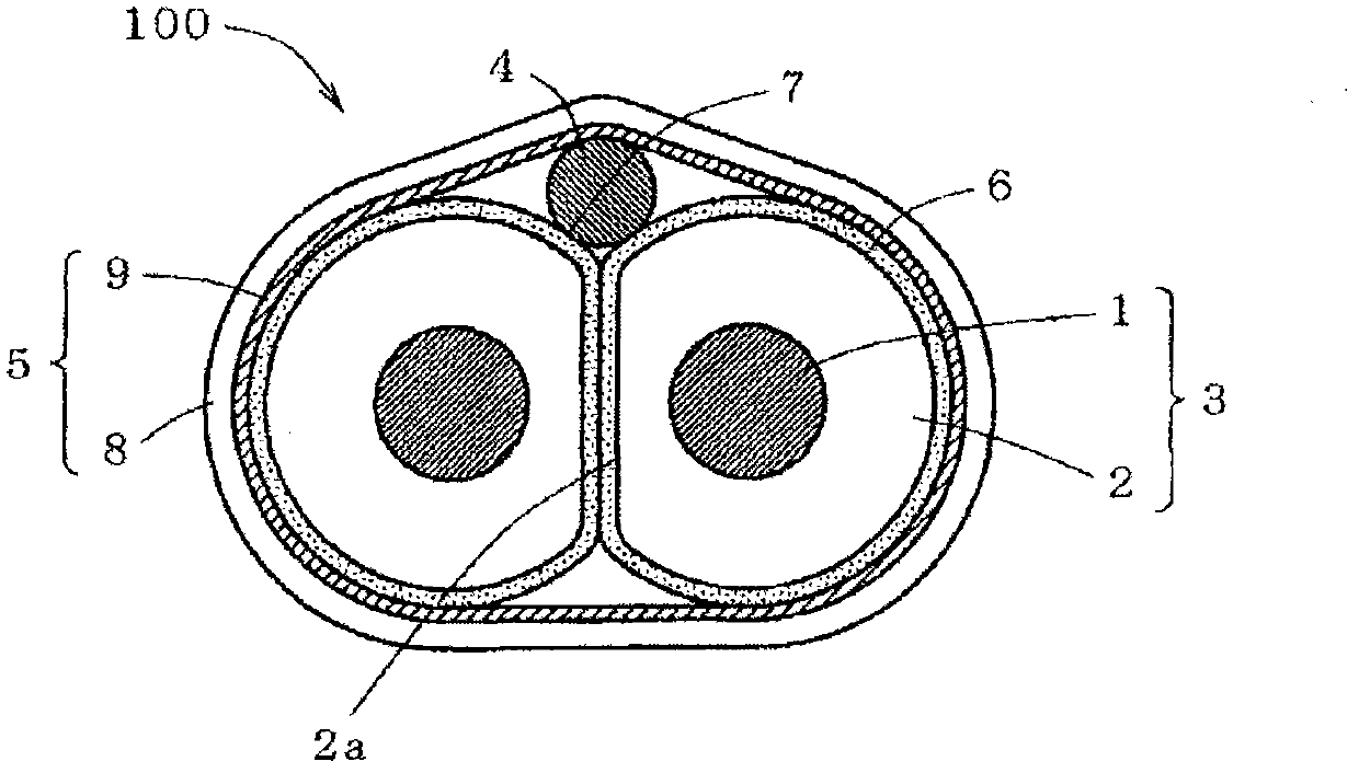
[0049] figure 1 It is a sectional view showing the differential signal cable of this embodiment.

[0050] Such as figure 1 As shown, the differential signal cable 100 of the present embodiment is provided with: two insulated wires 3 that are made of a signal wire 1 and an insulator 2 covering the wire 1 and are arranged in parallel contact; The drain wire 4 is additionally arranged longitudinally in the recess 7 formed between the two insulated cables 3 ; the shielding tape 5 that wraps the two insulated wires 3 and the drain wire 4 together.

[0051] The wire 1 is covered with an insulator 2 supplied by an extruder, whereby an insulated wire 3 is formed.

[0052] As the lead wire 1 used for the insulated wire 3 , a good electrical conductor such as copper, or a single wire or a strand obtained by performing plating or the like on these good electrical conductor...


PUM


Abstract

The invention provides a differential signal cable, a cable assembly and a multi-pair differential signal cable. The differential signal cable for transmitting high-speed digital differential signals of several Gbit / s or more is provided to minimize characteristic impedance mismatch and to repress increase in the skew, or increase in disturbance due to differential-mode to common-mode conversion. A differential signal cable comprises two insulated wires arranged parallelly in a contact, each of the two insulated wires comprising a conductor and an insulator jacketing the conductor, a fusion layer provided on the surface of each of the two insulated wires, a drain wire placed longitudinally in a recess created in the interstice between the two insulated wires, and a shield tape lapping around the two insulated wires and the drain wire together, wherein a surface of the insulator of each of the two insulated wires is partially deformed so as to have a flat portion and the two insulated wires are fused each other at the flat portions.

Description

technical field [0001] The present invention relates to a differential signal cable capable of transmitting high-speed digital signals over several Gbit / s for several meters to tens of meters with little signal waveform degradation, a cable assembly using the cable, and multiple pairs of differential signal cables. Background technique [0002] In devices such as servers, routers, and storage products that process high-speed digital signals of several Gbit / s or more, differential signals are used for signal transmission between devices or between substrates in devices. The so-called differential signal refers to a signal whose phase is reversed by 180° transmitted through two wires, and the difference of the received signals is synthesized on the receiving side and output. Since the current flowing in the two wires flows in the opposite direction, the electromagnetic wave radiated from the transmission line is small, and the noise received from the outside is equally overlap...

Claims


Application Information

Patent Timeline
Patent Type & Authority Applications(China)
IPC IPC(8): H01B7/00H01B7/02H01B7/17H01R24/00
CPCH01B11/1025H01B11/1091H01B11/203H01B11/1016
Inventor 杉山刚博南亩秀树塚本佳典
Owner PROTERIAL LTD
Learn More