Touch control signal scanning frequency determining method of touch panel

A technology of touch signal and scan times, applied in electrical digital data processing, input/output process of data processing, optics, etc., and can solve problems such as common voltage disturbance, low touch detection sensitivity, and long display data coupling time. , to achieve the effect of increasing the speed and improving the sensitivity

Active Publication Date: 2013-04-17
AU OPTRONICS CORP
View PDF2 Cites 0 Cited by
  • Summary
  • Abstract
  • Description
  • Claims
  • Application Information

AI Technical Summary

Problems solved by technology

[0005] Based on the above, the common voltage on the common electrode will be disturbed during the data coupling time, which will affect the touch sensor in the touch panel, so the touch driving pulse (for example, the pulse width is about 2.5μs) must be avoided. data coupling time
However, since the display data coupling time is too long, and the number of touch driving pulses in each gate line scanning cycle is set to be the same in the prior art, it will cause the touch scanning frame rate of the touch panel to rate) is too low, resulting in low touch detection sensitivity

Method used


Image

  • Touch control signal scanning frequency determining method of touch panel
  • Touch control signal scanning frequency determining method of touch panel
  • Touch control signal scanning frequency determining method of touch panel

Examples


Embodiment Construction

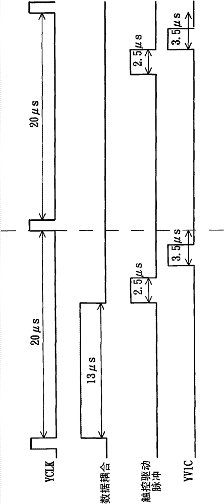
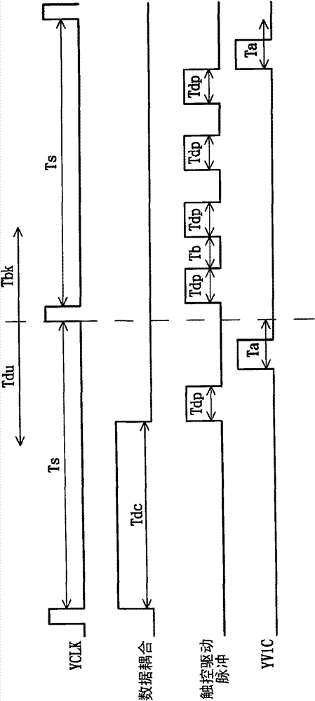
[0028] see figure 2 , which shows waveform diagrams of a plurality of signals related to the touch panel according to the embodiment of the present invention. Such as figure 2 As shown, a single frame period of the touch panel includes multiple gate line scanning periods T s , and a part of these gate line scanning periods Ts ( figure 2 Shown as an example) constitutes the data update period T within the frame period du , and these gate lines scan period T s other parts of the ( figure 2 One is shown as an example) to form a blanking period T in the frame period bk . As is well known, a touch panel usually includes a plurality of gate lines, a plurality of data lines for providing display data for display, and a plurality of pixels electrically coupled to these gate lines and data lines. The gate lines scan The period refers to the time period from the falling edge of a certain pulse in the scan control clock signal YCLK to the rising edge of the next pulse; in addi...


PUM


Abstract

A method for determining scanning times of touch driving pulse in a touch panel includes steps of: judging a current gate line scan period is in which one of a data updating time period and a blanking time period; if the current gate line scan period is in the data updating time period, setting a scanning times of touch driving pulse in the current gate line scan period to be a first value; and if the current gate line scan period is in the blanking time period, setting the scanning times of touch driving pulse in the current gate line scan period to be a second value. The first value is different from the second value, and a time for touch driving pulse scanning is non-overlapped with another time for providing display data to data lines of the touch panel in each scan line scan period.

Description

technical field [0001] The present invention relates to the technical field of touch panels, in particular to a method for determining the scanning times of a touch signal of a touch panel. Background technique [0002] With the development of technology, flat panel displays (such as liquid crystal displays) are widely used in mobile phones, notebook computers, desktop display devices and televisions due to their advantages of high image quality, small size, light weight and wide application range. In various consumer electronic products, it has gradually replaced the traditional cathode ray tube display and has become the mainstream of the display. [0003] The touch input device provides a new human-computer interaction interface, which is more intuitive and more humane in use. A touch panel can be obtained by integrating the touch input device with the flat panel display, which has both display and touch input functions. [0004] see figure 1 , which shows waveform dia...

Claims


Application Information

Patent Timeline
Patent Type & Authority Patents(China)
IPC IPC(8): G06F3/041
CPCG06F3/0416G06F3/041G02F1/13338G06F3/0412G06F3/04184G06F3/04166
Inventor 杨竣崴洪春龙许育民郑咏泽
Owner AU OPTRONICS CORP
Why Eureka
Try Eureka