
Constant-current circuit with characteristics of voltage compensation and zero potential switching

A technology of voltage compensation and switching characteristics, applied in the direction of adjusting electrical variables, control/regulation systems, instruments, etc., can solve the problems of power switch prone to heating, power loss, power waste, power switch Q3 heating, etc., and achieve the effect of simplifying the circuit layout

Inactive Publication Date: 2011-09-21
SKYNET ELECTRONICS
View PDF5 Cites 11 Cited by
  • Summary
  • Abstract
  • Description
  • Claims
  • Application Information

AI Technical Summary

Problems solved by technology

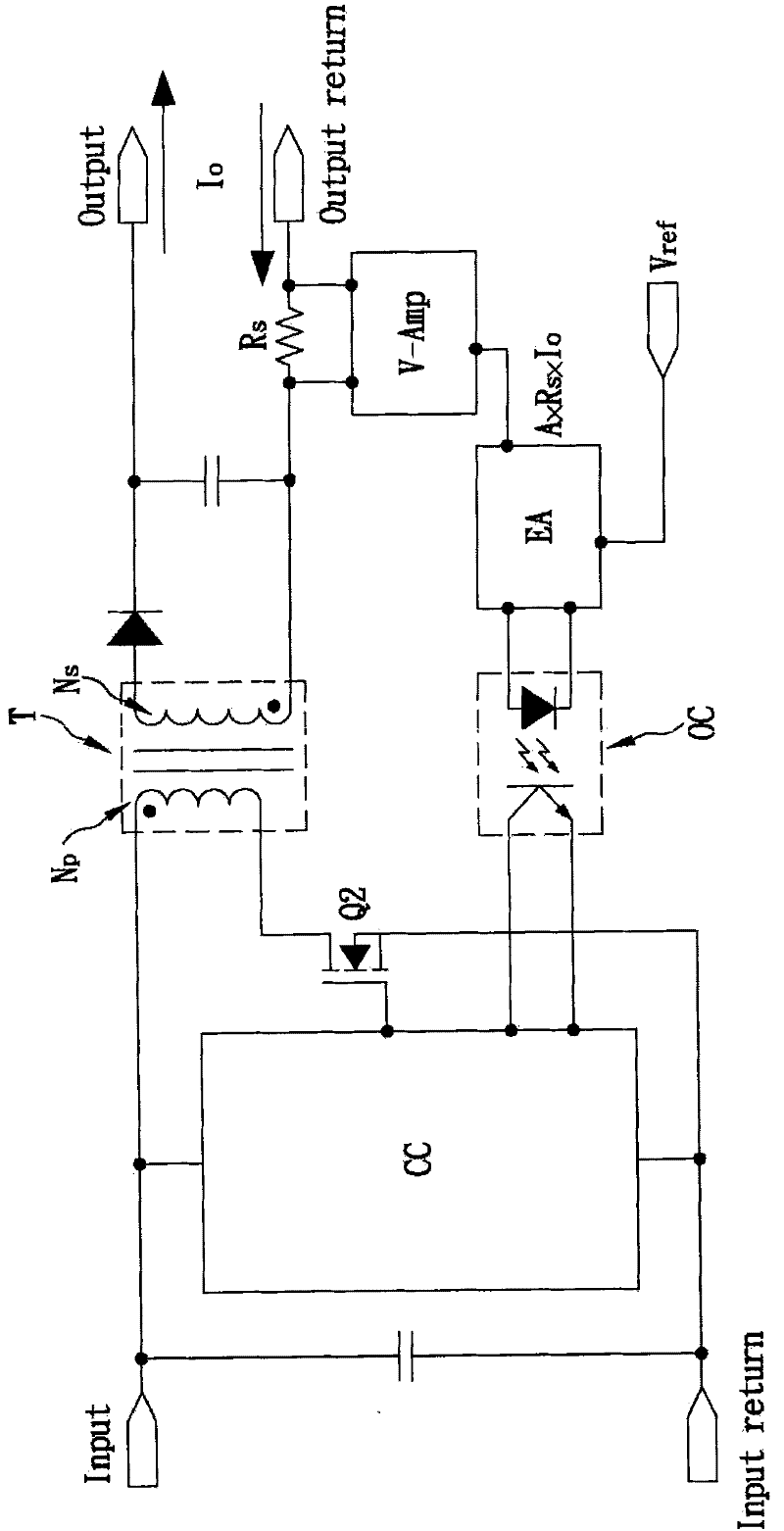
However, when image 3 When the shown constant current circuit operates in constant frequency DCM mode, refer to Figure 5 As shown, from the drain-source voltage waveform of the power switch Q3, it can be clearly seen that when the power switch Q3 is turned on, the drain-source voltage still exists as high as V bulk The voltage energy, the voltage energy V bulk When the power switch Q3 is turned on, all of it will be lost on the power switch Q3, thus it is very easy to cause the power switch Q3 to generate heat, so image 3 In the constant current circuit shown in the constant frequency DCM mode, its power switch Q3 will generate considerable power loss at the moment of conduction, resulting in unnecessary waste of electric energy
[0025] Most of the constant current circuits on the market today use image 3 The application circuit derived from the basic structure of the given current circuit, Image 6 The constant current circuit shown is a constant current circuit made by using a model FSEZ1016A current control IC produced by Fairchild Semiconductor. Figure 7 Shown is a constant current circuit made using a model FAN103 current control IC produced by Fairchild Semiconductor, Figure 8 Shown is a constant current circuit made using a current control IC of the type LNK605DG produced by Power Integrations. Therefore, these constant current circuits operate in the constant frequency DCM mode, and their power switches are prone to heat and burns at the moment of conduction. The problem of excessive power loss

Method used


Image

  • Constant-current circuit with characteristics of voltage compensation and zero potential switching
  • Constant-current circuit with characteristics of voltage compensation and zero potential switching
  • Constant-current circuit with characteristics of voltage compensation and zero potential switching

Examples


Embodiment Construction

[0070] For the convenience of purpose, structure and effect thereof of the present invention, do further understanding and understanding, give embodiment and cooperate accompanying drawing, describe in detail as follows:

[0071] The present invention is a constant current circuit with voltage compensation and zero potential switching characteristics. The constant current circuit can be applied to light-emitting diode (LED) lighting equipment as a drive circuit of light-emitting diodes, so that the output current of the drive circuit Can maintain a constant state, the constant current circuit is a single switch inverse magnetic converter (Single Switch Isolated Flyback Converter) operating in current mode, see Figure 9 shown, including a transformer T 5 , an input voltage filter capacitor C in , a linear resistance R line , an auxiliary resistor Ra , a RS flip-flop (latch) 10, a detection (Detection) circuit 20, a comparator (comparator) 30, a primary side power switch Q 5...


PUM


Abstract

The invention relates to a constant-current circuit with the characteristics of voltage compensation and zero potential switching. The constant-current circuit is a single-switch inverse magnetic converter, and comprises a control circuit, a detection resistor, a transformer, a partial voltage compensation circuit and a primary side power switch, wherein the control circuit acquires the primary side current information of the transformer by using the detection resistor, and can acquire a compensation signal from an input voltage by using the partial voltage compensation circuit, and control the threshold voltage of the primary side power switch according to the compensation signal, so that the peak voltage of the primary side current can be fixed at a reference voltage due to the compensating action of the compensation signal, and the output current of the constant-current circuit is kept in a constant state. The constant-current circuit provided by the invention has the advantages that under the conditions of not using a secondary constant-current detection circuit and a feedback circuit, all necessary information can be obtained at the primary side only by using cheap electronic components and very simplified circuit layouts, and a constant output current can be generated in a wide-area input voltage state.

Description

technical field [0001] The invention relates to a constant current circuit, especially a constant current circuit with voltage compensation and zero potential switching characteristics. The constant current circuit uses a detection resistor to obtain the information of the primary side current of a transformer, and uses a The voltage division compensation circuit obtains a compensation signal from an input voltage, and controls the threshold voltage of a primary side power switch accordingly, so that the peak voltage of the primary side current can be fixed at a reference voltage, so that the output current can be maintained in a constant state. Background technique [0002] In recent years, with the increasing awareness of energy saving, carbon reduction and environmental protection, traditional incandescent light bulbs or fluorescent lamps have been gradually replaced by light-emitting diode (hereinafter referred to as LED) lighting devices with lower power consumption and...

Claims


Application Information

Patent Timeline
Patent Type & Authority Applications(China)
IPC IPC(8): G05F3/16
Inventor 梁锦宏
Owner SKYNET ELECTRONICS
Learn More