Easily installed clothes hanger for electric heater

An electric heater and clothes drying rack technology is applied in the field of simple installation of clothes drying racks, which can solve the problems of inability to clamp, the feet are large in size, the clothes rack tubes are loose and fall off, etc., so as to achieve convenient packaging and transportation, small overall size, and material saving Effect

Inactive Publication Date: 2011-09-21
MIDEA GRP CO LTD
View PDF4 Cites 3 Cited by
  • Summary
  • Abstract
  • Description
  • Claims
  • Application Information

AI Technical Summary

Problems solved by technology

[0002] Existing electric heater is used clothes hanger structure as attached Figure 7 As shown, it includes two legs 6 and two hanger tubes 7. The hanger tubes 7 are inserted into the hanger legs 6 by an interference fit. Since the hanger tubes 7 are rigid components, they cannot be stretched or shortened, and they are easy to loosen in collisions.
During installation, it is necessary to assemble the two legs 6 and the two clothes hanger tubes 7 and then clamp them on the main body of the heat sink of the electric heater. The distance between them is not exactly the same, and it needs to be slightly adjusted before it can be installed on the heat dissipation body of the electric heater. During the adjustment, it is also easy to cause the assembled hanger tube to loosen and fall off
At the same time, the clothes hanger legs 6 are installed along the edge of the heat dissipation body through U-shaped clips. It is necessary to make longer clips to reliably fix the clothes hanger on the heat dissipation body, which leads to a large size of the legs and high material costs. At the same time, this The heat dissipation main body is installed along the edge and does not play a clamping role, and it is easy to tip over

Method used


Image

  • Easily installed clothes hanger for electric heater
  • Easily installed clothes hanger for electric heater
  • Easily installed clothes hanger for electric heater

Examples


Embodiment 1

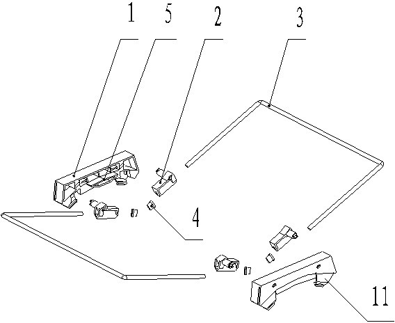
[0019] Such as figure 1 As shown, this embodiment includes a clothes hanger foot 1, a rotating block 2, and a clothes drying pole 3. The clothes hanger foot 1 is provided with one or more snap buttons 11, and the rotating block 2 is installed through its own buckle, rotating shaft or other hinges. On the hanger leg 1, it can rotate around the hinge shaft. There is a positioning device 5 on the hanger leg 1, which can limit the rotation angle of the rotating block 2 and play a positioning role; the rotating block 2 is provided with a through hole for installing clothes for drying The rod 3 and the clothes-drying rod 3 can slide along the axis of the through hole of the rotating block 2, so as to adjust the length of the clothes-drying rod 3; The sliding stroke size of clothes bar 3.

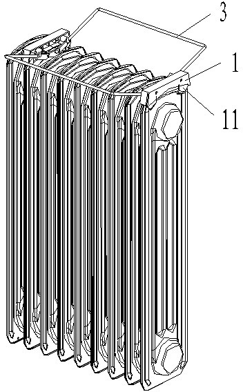
[0020] When this embodiment is used, the clothes hanger leg 1 is fixed on the reinforcing rib of the heat dissipation body of the electric heater through its snap button 11, and the clothes dryi...

Embodiment 2

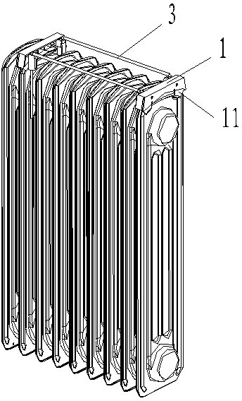
[0022] Such as Figure 4 , Figure 5 , Figure 6 As shown, the difference between the present embodiment and the first embodiment is that the two ends of the clothes-horse 3 are made into a bent structure and are directly inserted into the installation holes provided on the legs 1 of the clothes hanger. The clothes-horse 3 can rotate around the mounting hole of the clothes hanger leg 1 to realize the unfolding and closing action.


PUM


Abstract

The invention provides an easily installed clothes hanger for an electric heater. The clothes hanger comprises hanger legs and clothes poles. The clothes hanger is characterized in that the hanger legs are provided with one or more elastic buckles for buckling reinforcing ribs of radiating main bodies of the electric heater; and the clothes poles are hinged on the hanger legs. The clothes hanger has the following beneficial effects: the hanger legs are provided with the elastic buckles, so the hanger can be conveniently and reliably installed on the electric heater and can not tip over; the clothes poles are hinged on the hanger legs, so unfolding and folding of the clothes poles can be flexibly realized and falling apart can not occur; and at the same time, longer legs are unnecessary to be manufactured because the elastic buckles are used, so the clothes hanger has smaller overall dimension, saves materials and is convenient to package and transport.

Description

technical field [0001] The invention relates to an accessory of an electric heater, in particular to a clothes hanger for simple installation of the electric heater which is reliable and convenient to install. Background technique [0002] Existing electric heater is used clothes hanger structure as attached Figure 7 As shown, it includes two legs 6 and two hanger tubes 7. The hanger tubes 7 are inserted into the hanger legs 6 by an interference fit. Since the hanger tubes 7 are rigid components, they cannot be stretched or shortened, and they are easy to loosen in collisions. . During installation, it is necessary to assemble the two legs 6 and the two clothes hanger tubes 7 and then clamp them on the main body of the heat sink of the electric heater. The distance between them is not exactly the same, and it needs to be slightly adjusted before it can be installed on the heat dissipation body of the electric heater. During the adjustment, it is also easy to cause the asse...

Claims


Application Information

Patent Timeline
Patent Type & Authority Applications(China)
IPC IPC(8): D06F57/12
Inventor 李腾鹤张建聂勇
Owner MIDEA GRP CO LTD
Why Eureka
Try Eureka