
Electric assisted bicycle

An electric assist and bicycle technology, applied to bicycle accessories, bicycle auxiliary equipment, vehicle components, etc., can solve the problem that a large-capacity battery box cannot be installed, and achieve the effect of preventing the installation of the vehicle body

Inactive Publication Date: 2013-01-23
SANYO ELECTRIC CO LTD +1
View PDF1 Cites 0 Cited by
  • Summary
  • Abstract
  • Description
  • Claims
  • Application Information

AI Technical Summary

Problems solved by technology

If the width of the battery box becomes larger, the crank that connects the pedals and the battery box will become narrower, and there will be a danger of fingers being caught between the crank and the battery box. Therefore, it is necessary to make it impossible to install a large-capacity battery box until it is used. On the body of the conventional battery box

Method used


Image

  • Electric assisted bicycle
  • Electric assisted bicycle
  • Electric assisted bicycle

Examples


Embodiment Construction

[0037] Embodiments of the present invention will be described in detail below based on a power-assisted bicycle shown in the drawings.

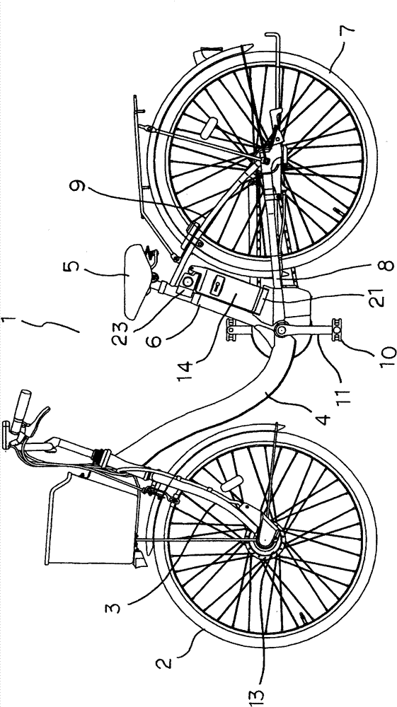
[0038] exist figure 1 Among them, the body of the power-assisted bicycle 1 includes: a front fork 3 supporting a front wheel 2, a down tube 4, a seat post 6 supporting a seat 5, a chain bracket 8 supporting a rear wheel 7, a seat bracket 9, and connecting pedals. 10 cranks 11 etc. A hub unit 13 with a built-in electric motor is arranged on the front wheel 2 , and a battery box 14 is mounted between the seat post 6 and the rear wheel 7 . A sensor (not shown) is equipped on the position where the pedaling force applied to the pedal 10 acts. ) to apply electric drive force.

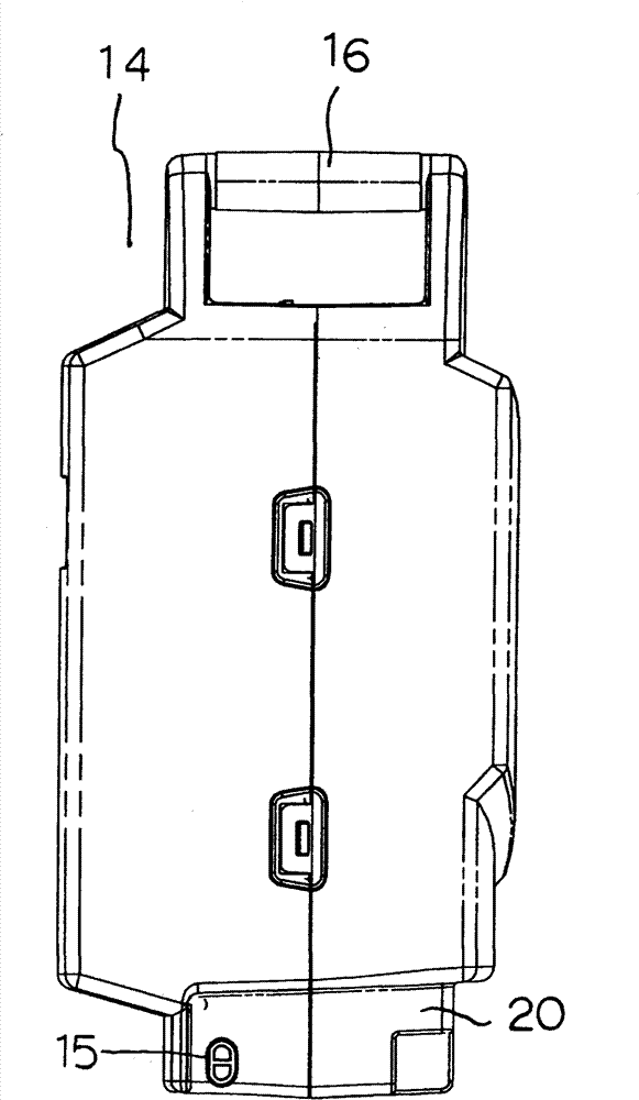
[0039] based on Figure 1 to Figure 8 , the battery box 14 is described in detail. A plurality of battery cells (not shown) are accommodated inside the battery box 14. The shaft portion 15 on the side surface is engaged with a not-illustrated groove portion formed in t...


PUM


Abstract

The invention discloses an electric assisted bicycle, in which the original battery box can be installed on a body loading a high-capacity battery box and the high-capacity battery box cannot be installed on a body having the original battery box. The body is provided with a terminal plate (21) having a connection terminal connected with an electric unit. The battery box (14) having a connection terminal connected with the connection terminal is installed so as to swing when being supported on the terminal plate (21). A locking mechanism (23) is arranged on the body. The locking mechanism (23) and the battery box (14) are clamped so as to fix the battery box (14) in a free clamping separation way. A bump (17) is formed on the battery box towards the locking mechanism (23). A notch part (25) preventing the bump (17) from being in butting joint is formed on the locking mechanism (23).

Description

technical field [0001] The present invention relates to an improvement of a power-assisted bicycle having a human-powered drive system that transmits pedaling force based on pedals and a motor drive system that transmits power from an electric unit. Background technique [0002] Conventionally, electric-assisted bicycles are configured to detect pedaling force by pedals, and transmit electric driving force corresponding to the pedaling force to assist human power. A battery box for supplying electric power to a power unit that outputs electric driving force is detachably mounted between a seat post and a rear wheel of a vehicle body as disclosed in Patent Document 1, for example. [0003] The battery box is configured to swing around the hooked portion as a fulcrum while the lower end is hooked to the battery bracket arranged on the vehicle body, and the upper end side of the battery box is engaged with a locking mechanism arranged on the vehicle body. [0004] In recent ye...

Claims


Application Information

Patent Timeline
Patent Type & Authority Patents(China)
IPC IPC(8): B62M23/02B62J11/00
Inventor 桑原将吾追风达郎
Owner SANYO ELECTRIC CO LTD
Learn More