
Automatic back scrubbing machine

A back-wiping machine and automatic technology, which is applied to household appliances, applications, sanitary equipment and other directions, can solve the problems of human injury, easy slipping, and unsatisfactory back-wiping effect, and achieve the effect of avoiding sticking and good wiping effect.

Inactive Publication Date: 2011-09-21
YANGZHOU WEIBANG GARDEN MACHINE
View PDF6 Cites 9 Cited by
  • Summary
  • Abstract
  • Description
  • Claims
  • Application Information

AI Technical Summary

Problems solved by technology

[0004] The rotating movement of the back rubbing head generates a rotational moment, which pushes the human body in the direction of the back rubbing head rotation, making people unstable and prone to slipping
When the position of the back rubbing head is fixed, the contact area with the back of the human body is small, resulting in unsatisfactory back rubbing effect
Therefore, the back rubbing head is driven to reciprocate through the crank linkage mechanism. While the back rubbing head is reciprocating, it can also move up and down as a whole to wipe all heights of the back, but the crank linkage mechanism can realize the reciprocating stroke. very small
And because the reciprocating movement of the back rubbing head needs to open a movement slot on the back rubbing machine cover, without paying attention, people's limbs are easy to reach into the back rubbing machine and be caught, causing harm to the human body

Method used


Image

  • Automatic back scrubbing machine
  • Automatic back scrubbing machine
  • Automatic back scrubbing machine

Examples


Embodiment Construction

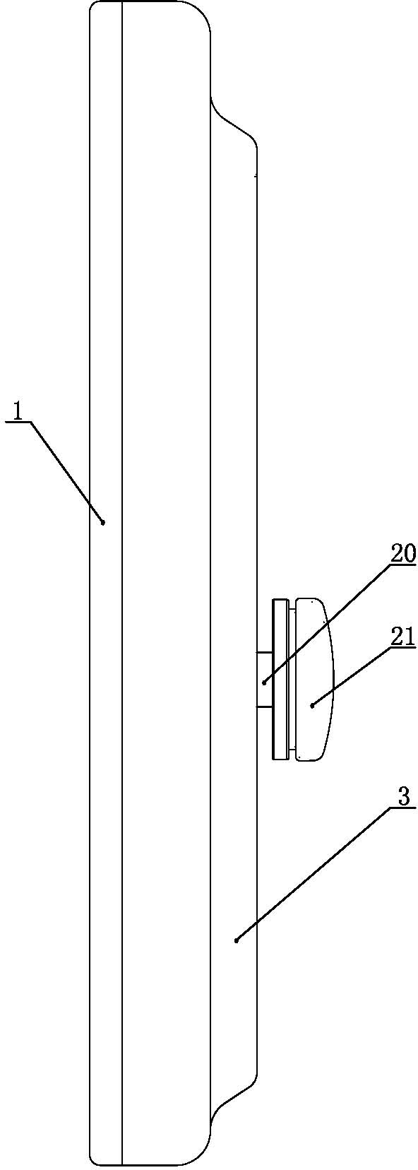
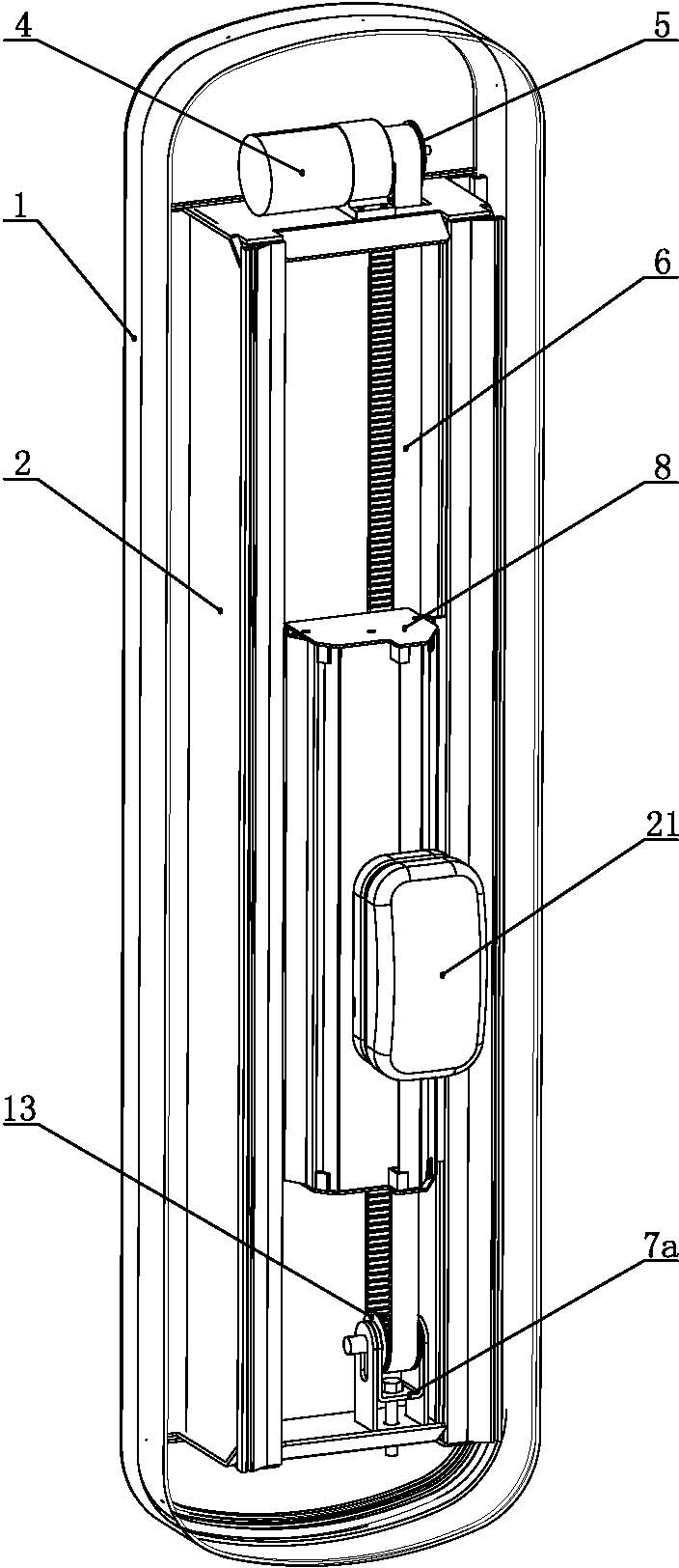
[0029] Such as figure 1 and figure 2 As shown, the automatic back rubbing machine of the present invention includes a back plate 1, a casing 3 and a back rubbing head 21. The casing 3 is provided with a long groove 3a, and a small slider 20 protrudes from the long groove 3a and is connected to the back of the back rubbing head 21. .

[0030] Such as image 3 , Figure 4 and Figure 5 As shown, the automatic back rubbing machine of the present invention also includes a lifting mechanism and a back and forth head reciprocating mechanism. The two sides of the back plate 1 are connected with side plates 2 connected with the back plate 1, and the side plates 2 are symmetrically arranged along the back plate. Large slider guides extending in height. The lifting mechanism includes a lifting motor 4, a driving pulley 5, a belt 6, a driven pulley 7 and a large slider 8, the driving pulley 5 is connected to the output shaft of the lifting motor 4, and the belt 6 connects the drivi...


PUM


Abstract

The invention relates to an automatic back scrubbing machine, comprising a back plate, a cover shell, a back scrubbing head and a large slider moving along the height direction of the back plate, wherein the large slider is of a hollow cuboid structure; the inner walls of the two sides of the large slider are respectively provided with a small slider seat guide groove; an inner cavity of the large slider is provided with a driving chain wheel, a driven chain wheel and a chain which connects the driving chain wheel and the driven chain wheel in a transmission manner; the driving chain wheel is arranged on an output shaft of a motor of the back scrubbing head; a chain wheel shaft of the driven chain wheel is supported on a bearing block; the motor of the back scrubbing head and the bearing block are arranged at the outer side of the bottom wall of the large slider; the chain is connected with a cylindrical boss lower block by a chain long pin; a boss upper block is sheathed outside the periphery of the boss lower block and is embedded in the back of a small slider seat; the two sides of the small slider seat are respectively positioned in the small slider seat guide grooves and can move respectively along the small slider seat guide grooves; the front surface of the small slider seat is connected with a small slider; and the top end of the small slider is fixedly connected with the back scrubbing head. A boss moves along the chain and drives the back scrubbing head to move up and down, so that a larger reciprocating stroke can be realized.

Description

technical field [0001] The invention relates to a bathing facility, in particular to an automatic back scrubbing machine. Background technique [0002] When people take a bath, it is inconvenient to scrub their backs, and they often need to ask others to help scrub their backs. Because of this, various bathing facilities to help scrub their backs have emerged as the times require. [0003] Most of the existing back rubbing machines use a single motor to directly connect with the back rubbing head through the output shaft, and drive the back rubbing head to rotate through the rotation of the motor, or drive the back rubbing head to do reciprocating motion through the crank linkage mechanism; On the exercise frame, the exercise frame is connected with the driving mechanism, and the driving mechanism drives the back rubbing head to move up and down, so as to realize the function of automatically scrubbing and massaging the back of the human body. [0004] The rotational moveme...

Claims


Application Information

Patent Timeline
Patent Type & Authority Applications(China)
IPC IPC(8): A47K7/04
Inventor 鞠苏成谢春干
Owner YANGZHOU WEIBANG GARDEN MACHINE
Learn More