Method and device for transmitting data based on VLL (Virtual Lease Line)

A data transmission method and decapsulation technology, applied in the direction of digital transmission system, transmission system, data exchange network, etc., can solve the problems of inability to meet requirements, rapid increase, and high price

Active Publication Date: 2011-09-14
NEW H3C TECH CO LTD
View PDF3 Cites 24 Cited by
  • Summary
  • Abstract
  • Description
  • Claims
  • Application Information

AI Technical Summary

Problems solved by technology

[0003] Initially, telecom operators provided links for enterprises in the form of leased lines. The main disadvantages of this method are: it is not suitable for the current characteristics of enterprises with many branches and fast growth, and the price is relatively expensive and difficult to manage.
When there are multiple local ACs on the PE device and need to establish connections with multiple ACs on the opposite end, one VLL PW connection on the public network side cannot meet the requirements, and multiple VLL PW connections must be established between the two PE devices; However, when there are multiple local AC access sides on the PE device and need to establish a connection with an AC on the opposite end, the VLL PW connection cannot meet the requirements.
It can be seen that the existing VLL cannot support multi-point access between the local AC and the peer AC in a VLL PW connection

Method used


Image

  • Method and device for transmitting data based on VLL (Virtual Lease Line)
  • Method and device for transmitting data based on VLL (Virtual Lease Line)
  • Method and device for transmitting data based on VLL (Virtual Lease Line)

Examples


Embodiment 1

[0041] This embodiment describes the implementation of supporting multiple ACs at the local end and multiple ACs at the remote end to access the same ALL instance. In this embodiment, a VLL public network connection supports interconnection between multiple local ACs and multiple peer ACs, and the number of local ACs is the same as the number of peer ACs. One local AC is bound to one peer AC to form a fixed Point-to-point connection, while there is only one public PW on the public network side. This kind of networking is like directly aggregating multiple ordinary VLL connections on the public network side.

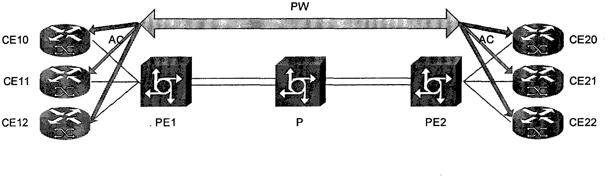
[0042] The networking architecture of this embodiment can be as follows figure 2 shown. A VLL PW connection is established between PE1 and PE2. Three user access devices CE10, CE11, and CE12 are connected to PE1, and there are three corresponding ACs: AC10, AC11, and AC12. Three user access devices are connected to PE2. CE20, CE21, and CE22, and correspondingly there a...

Embodiment 2

[0063] Embodiment 2 is obtained by improving Embodiment 1, aiming at figure 2 As shown in the network architecture, that is, when the number of ACs on the AC side of the PE equipment at both ends of the PW is equal, the corresponding A-TAG can be assigned to each connection from the local AC to the peer AC, so that the The A-TAG mapping relationship table is configured on the PE device. For example, for figure 2 In the shown network architecture, A-TAG_0 may be allocated for the connection between AC10 and AC20, A-TAG_1 may be allocated for the connection between AC11 and AC21, and A-TAG_2 may be allocated for the connection between AC12 and AC22. Take the case where user CE10 sends packets from AC10 to PE1. The packet transmission process mainly includes:

[0064]When a packet from the user CE10 side (the packet carries an A-TAG, and the A-TAG is A-TAG_0) enters PE1, PE1 performs necessary encapsulation processing on the packet and sends the packet to the PW, where , the...

Embodiment 3

[0067] This embodiment describes an implementation manner in which one AC at the local end and multiple ACs at the opposite end access the same VLL instance. In this embodiment, the PE device with multiple ACs sends and receives packets similarly to Embodiment 1, but on the PE device with one AC, multiple A-TAGs need to be bound to the same AC. Similarly, in order to provide more flexible access, it is necessary to establish a mapping table between LOCALA-TAG and Remote A-TAG on the AC side of each PE device, so that the PE device at the sending end of the packet can determine which address to send the packet to at the peer end through the mapping table. An AC, or the PE device at the message receiving end decides which local AC to send the message received from the peer end through the mapping table.

[0068] The networking architecture of this embodiment can be as follows Figure 4 shown. Take PE2 as an example for description. PE1 and PE2 are PE devices at both ends of t...


PUM


Abstract

The invention discloses a method and device for transmitting data based on a VLL (Virtual Lease Line), which are applied to a MPLS L2VPN (Multi-Protocol Label Switching L2 Virtual Private Network). At least two AC (Attached Circuits) exist on the AC side of at least one PE (Provider Edge) equipment of PE equipment at the two ends of a VLL PW (Virtual Lease Line Pseudo Wire). The method comprises the following steps of: distributing an A-TAG (Access-Tag) for the ACs of the PE equipment at the two ends of the PW respectively and configuring the A-TAG mapping relation of the PE equipment at the two ends on the PE equipment at the two ends of the PW; after the PE equipment at one end of the PW receives a message from the AC at the same end, acquiring the A-TAG of the AC at the same end, acquiring the A-TAG of the PE equipment at an opposite end corresponding to the A-TAG of the AC at the same end according to the A-TAG mapping relation configured at the same end, encapsulating the message into a PW channel message which carries the A-TAG of the PE equipment at the opposite end, and transmitting the PW channel message to the PE equipment at the opposite end through the PW; and after the PE equipment at one end of the PW receives the PW channel message from the PW, de-encapsulating and forwarding a de-encapsulated message through the corresponding AC at the same time according to the carried A-TAG. By adopting the method and the device, supporting of multi-point access of a local AC and the AC at the opposite end in a VLL PW link can be realized.

Description

technical field [0001] The present invention relates to the field of communication technology, in particular to a VLL-based data transmission method and device thereof. Background technique [0002] With the development of society, more and more enterprises are expanding their distribution scope, and the mobility of company employees is also increasing. It is urgent for telecom operators to provide link connections so that enterprises can include all branches to form their own enterprise network. And it is convenient for employees of the company to access the internal network of the enterprise very conveniently in places outside the enterprise. [0003] Initially, telecom operators provided links to enterprises in the form of leased lines. The main disadvantages of this method are: it is not suitable for the current characteristics of enterprises with many branches and rapid growth, and it is relatively expensive and difficult to manage. Since then, with the rise of ATM (As...

Claims


Application Information

Patent Timeline
IPC IPC(8): H04L12/56H04L47/43
Inventor 宋小恒
Owner NEW H3C TECH CO LTD
Why Eureka
Try Eureka