
The static power consumption elimination circuit of the chip input pull-up resistor

A technology of static power consumption and circuit elimination, applied in electrical components, electronic switches, pulse technology, etc., can solve the problem of large power consumption and achieve the effect of eliminating DC current

Active Publication Date: 2015-11-25
SUZHOU POWERLINK MICROELECTRONICS
View PDF5 Cites 0 Cited by
  • Summary
  • Abstract
  • Description
  • Claims
  • Application Information

AI Technical Summary

Problems solved by technology

If a chip has multiple input terminals with pull-up resistors, and all of them are driven by external low level, the power consumption will be very large, which is in some systems that require low power consumption, especially in the case of battery power. is unacceptable

Method used


Image

  • The static power consumption elimination circuit of the chip input pull-up resistor
  • The static power consumption elimination circuit of the chip input pull-up resistor

Examples


Embodiment Construction

[0014] Preferred embodiments of the present invention will be described in detail below in conjunction with the accompanying drawings.

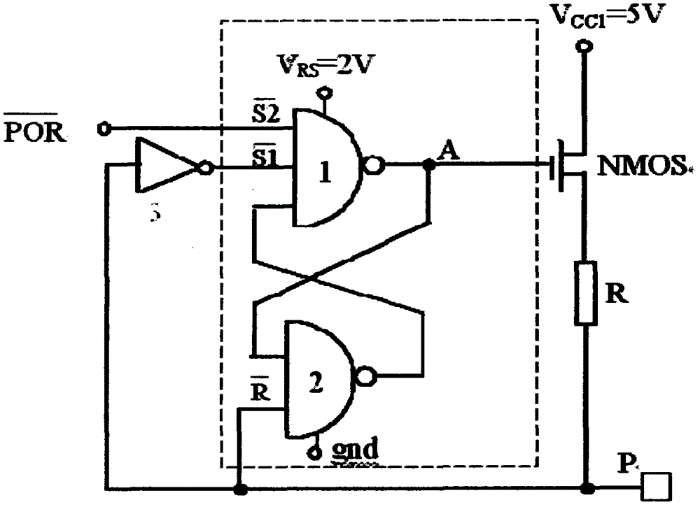
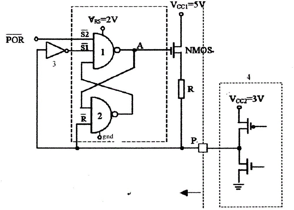
[0015] Such as figure 1 As shown, the static power consumption elimination circuit of the pull-up resistor at the input end of the chip includes an NMOS tube and a resistor R, and the NMOS tube and the resistor R are connected in series to the internal power supply V of the chip. cc1 Between the NMOS transistor and the input port P of the chip, the gate of the NMOS transistor is connected to the output end of a control circuit, and the input port of the chip is connected to one or more input ends of the control circuit, thereby forming a closed-loop circuit structure. The control circuit includes an RS flip-flop and an inverter 3, the RS flip-flop is composed of a first NAND gate 1 and a second NAND gate 2, the first NAND gate 1 is a three-terminal input NAND gate, and the second NAND gate NAND gate 2 is a two-terminal input NAND gate, and t...


PUM


Abstract

The invention discloses a cancelling circuit for quiescent power consumption of a pull-up resistor on a chip input terminal. The cancelling circuit in the invention comprises an NMOS (N-Mental-Oxide-Semiconductor) tube which is taken as the pull-up resistor, a power source in a chip, a chip input port, a control circuit provided with an output terminal and input terminals, and an input terminal arranged on the control circuit to connect with an electrifying reset signal in the chip wherein the NMOS tube is in a series connection between the power source and the chip input port, a grid of the NMOS tube is connected to the output terminal of the control circuit, and the chip input port connects with one or more input terminals of the control circuit. When the electrifying reset signal is in low level, the control circuit switches the NMOS tube on; when the chip input port is in low level, the control circuit switches the NMOS tube off. By adopting the circuit, no matter how the electrical level brought to the chip input port by an external drive circuit changes, no quiescent current passes through the pull-up resistor. Thus, no quiescent power consumption is generated.

Description

technical field [0001] The invention relates to the field of integrated circuits, in particular to a circuit for eliminating the static power consumption of a pull-up resistor at the input end of a chip. Background technique [0002] In some integrated circuits, it is necessary to add pull-up resistors to certain input terminals in order to determine the initial state of these input terminals during operation, or to reduce external interference. In actual application, the common pull-up resistor structure will consume a certain amount of static power consumption. First of all, when the external drive circuit adds a low level to the input pin, it will form a DC path from the on-chip power supply, the pull-up resistor to the ground, thus consuming a certain amount of static power consumption on the pull-up resistor; secondly, even if the external drive circuit gives the input The pin is added to a high level, and when its voltage value is inconsistent with the on-chip power s...

Claims


Application Information

Patent Timeline
Patent Type & Authority Patents(China)
IPC IPC(8): H03K17/78
Inventor 韩兴成韩雨亭
Owner SUZHOU POWERLINK MICROELECTRONICS
Learn More