
Switching power supply as well as control circuit and method thereof

A technology of switching power supply and switching voltage, which is applied in the layout of electric lamp circuit, electric light source, electroluminescent light source, etc., can solve problems such as damage of switching power supply, failure of control IC to detect protection measures in time, etc.

Active Publication Date: 2011-09-14
CHENGDU MONOLITHIC POWER SYST
View PDF3 Cites 43 Cited by
  • Summary
  • Abstract
  • Description
  • Claims
  • Application Information

AI Technical Summary

Problems solved by technology

In some special cases, due to the effect of leading edge blanking, the control IC cannot detect the overcurrent situation in time and take protective measures, resulting in damage to the switching power supply

Method used

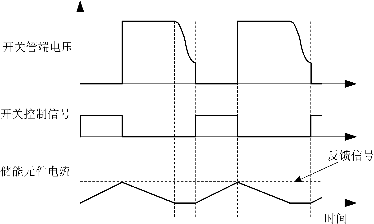
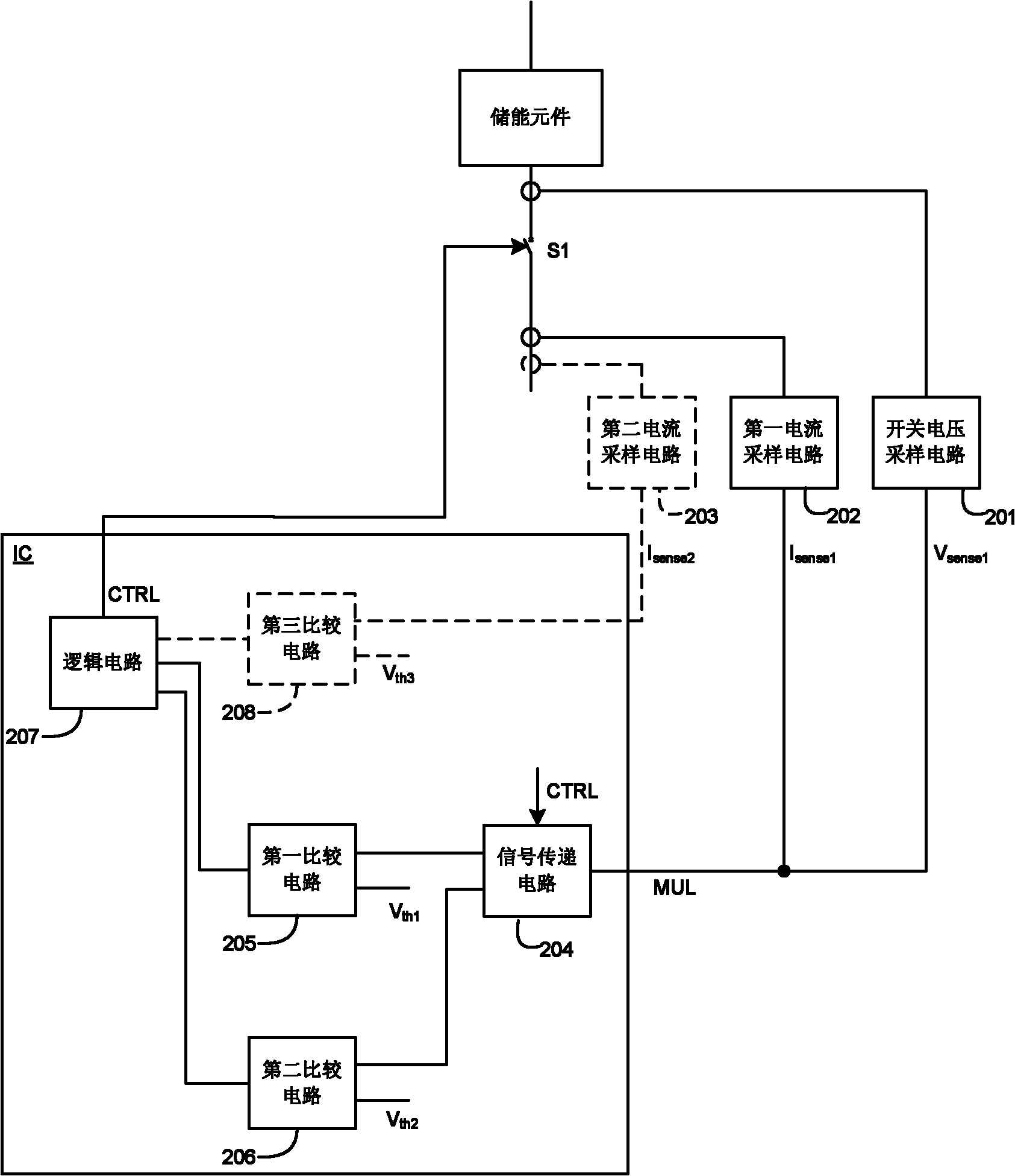
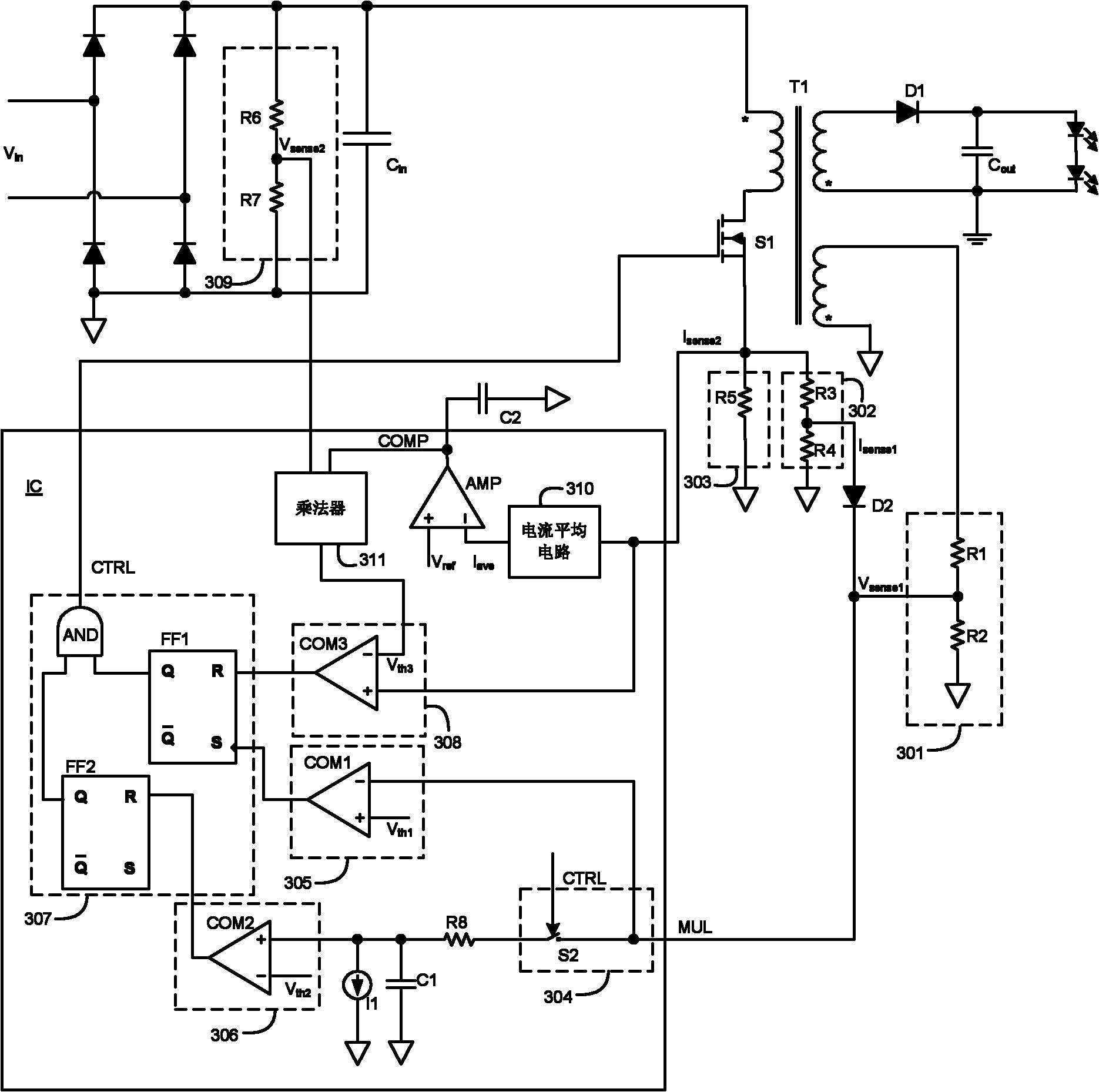

Image

  • Switching power supply as well as control circuit and method thereof
  • Switching power supply as well as control circuit and method thereof
  • Switching power supply as well as control circuit and method thereof

Examples


Embodiment Construction

[0025] Specific embodiments of the present invention will be described in detail below, and it should be noted that the embodiments described here are only for illustration, not for limiting the present invention.

[0026] figure 2 It is a block diagram of a switching power supply according to an embodiment of the present invention, including a first switching tube S1 , an energy storage element, a switching voltage sampling circuit 201 , a first current sampling circuit 202 and a control circuit IC. The first switching transistor S1 may be any controllable semiconductor switching device, such as a Metal Oxide Semiconductor Field Effect Transistor (MOSFET), an Insulated Gate Bipolar Transistor (IGBT) and the like. The energy storage element is electrically coupled to the first switch tube S1, and when the first switch tube S1 is turned on and off, the energy storage element stores and outputs energy. The energy storage element can be an inductor or a transformer.

[0027] T...


PUM


Abstract

The invention discloses a switching power supply and a control circuit and method thereof. The control circuit is provided with multi-functional pins for receiving first current sampling signals and switching voltage sampling signals. The control circuit is used for comparing signals on the multi-functional pins with a second threshold value when a switching tube is switched on; and the control circuit is used for comparing the signals on the multi-functional pins with a first threshold value when the switching tube is switched off, thus controlling switch-on and switch-off of the switching tube. The control circuit is used for receiving second current sampling signals and switching off the switching tube when the second current sampling signals are more than a third threshold value. The first current sampling signals independent of the second current sampling signals are used for realizing overcurrent protection, thus the limited value of overcurrent can be adjusted, thereby providing sufficient protection for the switching power supply. In addition, the multi-functional pins are used for receiving the first current sampling signals and the switching voltage sampling signals simultaneously, thus simplifying the circuit and saving the cost and the volume.

Description

technical field [0001] Embodiments of the present invention relate to a switching power supply, in particular, to a switching power supply and its control circuit and control method. Background technique [0002] Today, many electronic devices require DC voltage power supply, and light-emitting elements such as light-emitting diodes (LEDs) also need DC current to drive, and these DC signals usually come from switching power supplies. Switching power supplies use transformers or inductors as energy storage elements. For example, a transformer is used as an energy storage element in a flyback converter. A switch tube is electrically coupled to the primary winding of the transformer. The control circuit controls the switch tube to be turned on and off, so that the energy is alternately stored in the transformer or is passed to the secondary of the transformer, which in turn drives the LEDs. [0003] There are many control methods for switching power supplies, which are mainly...

Claims


Application Information

Patent Timeline
Patent Type & Authority Applications(China)
IPC IPC(8): H02M3/335H05B37/02H05B44/00
CPCY02B20/341H05B33/0815H02M3/33507H05B33/08H05B45/382Y02B20/30H05B45/375H05B45/385H05B45/38H05B45/3725
Inventor 张永良席小玉蔡家利
Owner CHENGDU MONOLITHIC POWER SYST
Learn More