
Dual-claw polar multi-phase excitation generator

A generator and double claw pole technology, applied in the shape/style/structure of winding conductors, etc., can solve the problems of low power, large relative surface area and high cost of generators for vehicle generators, and achieve small synchronous reactance and number of phases. The effect of many, low excitation cost

Inactive Publication Date: 2011-09-14
邓素华
View PDF5 Cites 3 Cited by
  • Summary
  • Abstract
  • Description
  • Claims
  • Application Information

AI Technical Summary

Problems solved by technology

However, they also have the disadvantages of medium power (about 1KW) voltage regulation difficulty and high cost of voltage regulation
As disclosed in CN1677793, the "four-phase permanent magnet generator for hybrid electric vehicles" adopts the "rectifier regulator for hybrid vehicles" disclosed in CN1707938 to realize rectification and voltage stabilization, and has achieved good economic and social benefits. However, an important problem faced is the difficulty of voltage stabilization and the high cost of voltage stabilization leading to the high cost of the entire generator.
[0005] In order to solve the above problems, people began to focus on the hybrid excitation generator, but the hybrid excitation generator has many disadvantages, such as large volume and weight, complex structure, high excitation cost, high cost of the whole machine, etc.
[0006] In response to the above problems, someone proposed a claw-pole multi-phase excitation generator, but the existing problem is: due to the small power of the vehicle generator and the small number of claw poles, if a multi-phase (greater than or equal to 4) structure is used, that is, every One claw pole corresponds to multiple stator core poles, resulting in fewer claw poles and larger relative surface area; in order to make the magnetization uniform, more claw pole surfaces must be processed, which makes the process complicated and the manufacturing cost high
So now it is difficult to see multi-phase claw pole type small and medium power excitation generator

Method used


Image

  • Dual-claw polar multi-phase excitation generator
  • Dual-claw polar multi-phase excitation generator
  • Dual-claw polar multi-phase excitation generator

Examples


Embodiment Construction

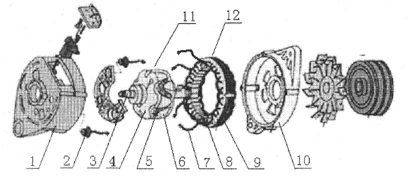
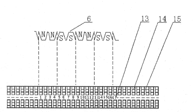
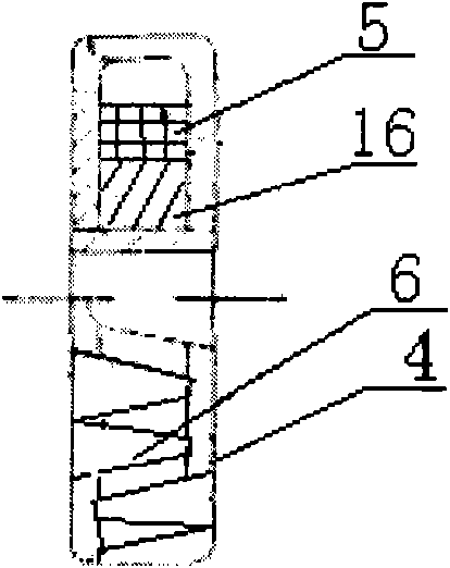
[0029] 1. Rear cover; 2. Diode; 3. Shaft; 4. Flange; 5. Excitation winding; 6. Claw pole; 7. Tail end of armature winding; 8. Armature winding; 9. Stator core ;10, front end cover; 11, rotor; 12, stator; 13, stator core pole number; 14, stator core pole; 15, stator core wire groove; 16, rotor core; 17, voltage stabilizer; 18 , Four-phase bridge rectifier; 19, permanent magnet rotor core; 20, cast bracket; 21, pole shoe; 22, non-magnetic screw; 23, permanent magnet.

[0030] Combine below figure 1 , figure 2 , image 3 , Figure 4 The present invention is described further:

[0031] The double-claw-pole multi-phase excitation generator comprises a front end cover 10, a rear end cover 1, a four-phase bridge rectifier 18, a voltage stabilizer 17, a rotating shaft 3, a stator composed of a stator core 9 and an armature winding 8, composed of The rotor consists of rotor core 16, claw pole 6, flange 4, and field winding 5; the first end of the armature winding 8 is connected t...


PUM


Abstract

The utility model provides a dual-claw polar multi-phase excitation generator belonging to the field of automobile electric apparatus. The dual-claw polar multi-phase excitation generator is mainly characterized in that armature windings are n-phase identical armature windings; each phase of the n phases spans n poles on a stator core respectively and is embedded with wires in sequnce; the phase difference of the armature windings is 360 / n degree, wherein n is an integer more than or equal to 4; and every two adjacent claw poles on each flange correspond to every n poles on a stator core. The dual-claw polar multi-phase excitation generator has the advantages that a rectifier has little heating quantity, long service life, simple and reliable voltage stabilizing and low cost, the generator is claw pole shaped, can be machined simply, can be magnetized uniformly, has high utilization degree, low whole-machine cost, and the like.

Description

technical field [0001] The invention provides a double-claw pole type multi-phase excitation generator, which belongs to the field of automobile electric appliances. Background technique [0002] As a pillar industry in our country, the automobile industry is playing an increasingly important role in the social economy. The generator is an important electrical appliance in the car, and has formed a large research field and industry. With the improvement of people's requirements for car comfort, the power of car generators is also increasing. The current generators of mid-to-high-end cars are generally around 1KW. [0003] With the increase of generator power, the number of phases of its stator winding transitions from single-phase (about 150W), two-phase (about 450W) to three-phase (about 900W) commonly used now, but when the generator power reaches about 1KW , There will be problems such as too large voltage fluctuation, enhanced armature reaction, reduced efficiency, inc...

Claims


Application Information

Patent Timeline
Patent Type & Authority Applications(China)
IPC IPC(8): H02K3/28H02K7/18
Inventor 柳小伟邓素华
Owner 邓素华
Learn More