Electromagnet with current separation channel

An electromagnet and sorting technology, applied in the field of electromagnets, can solve the problem of easy burnout of the coil, and achieve the effect of prolonging the service life

Inactive Publication Date: 2011-09-14
XIAMEN TAIHANG TECH
View PDF2 Cites 3 Cited by
  • Summary
  • Abstract
  • Description
  • Claims
  • Application Information

AI Technical Summary

Problems solved by technology

To reduce the operating current, the number of coil turns must be increased; the increase in the number of turns will reduce the diameter of the wire; the diameter of the coil is small, and the coil is easy to burn out when a large current comes.

Method used


Image

  • Electromagnet with current separation channel
  • Electromagnet with current separation channel
  • Electromagnet with current separation channel

Examples


Embodiment Construction

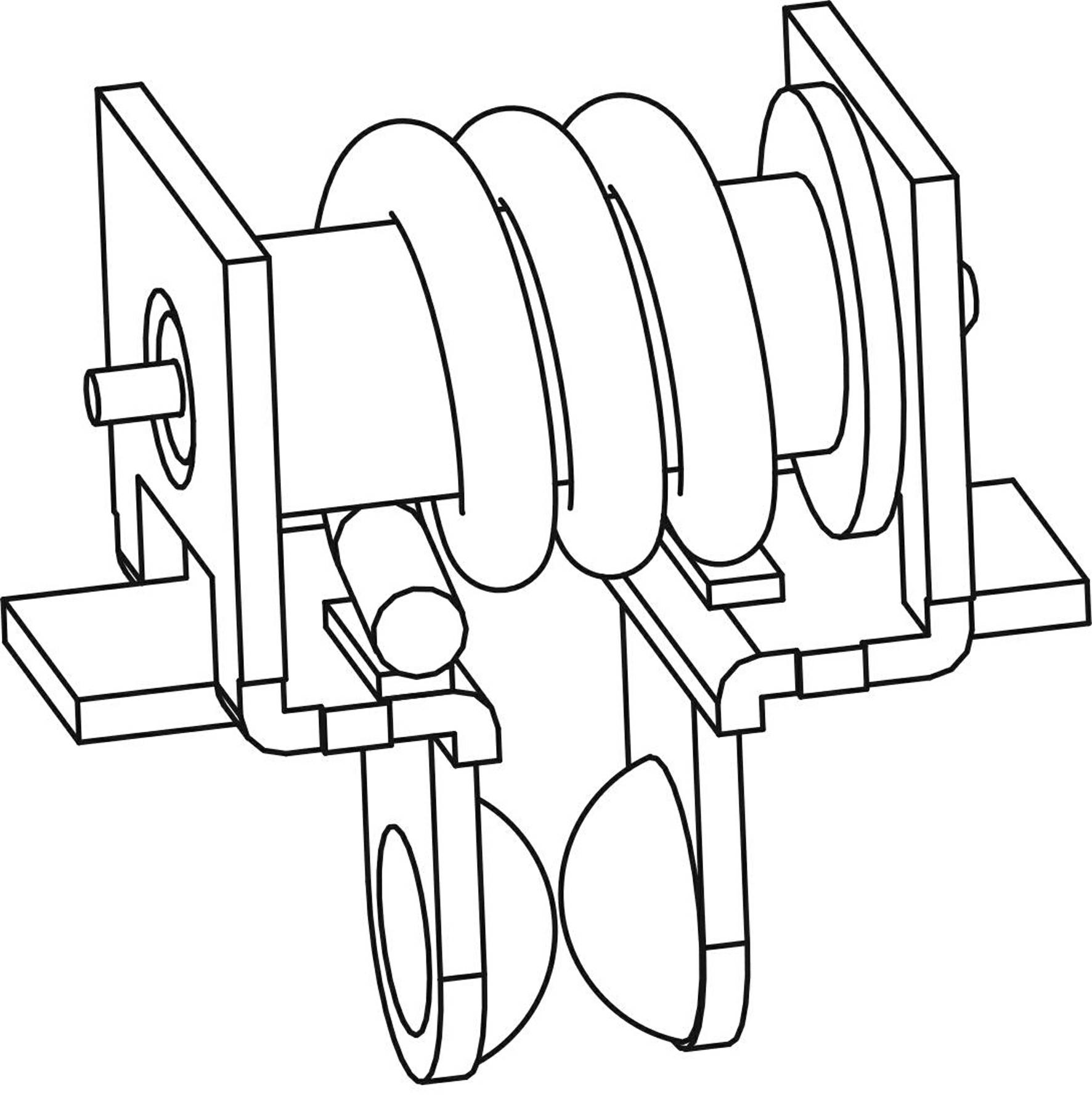
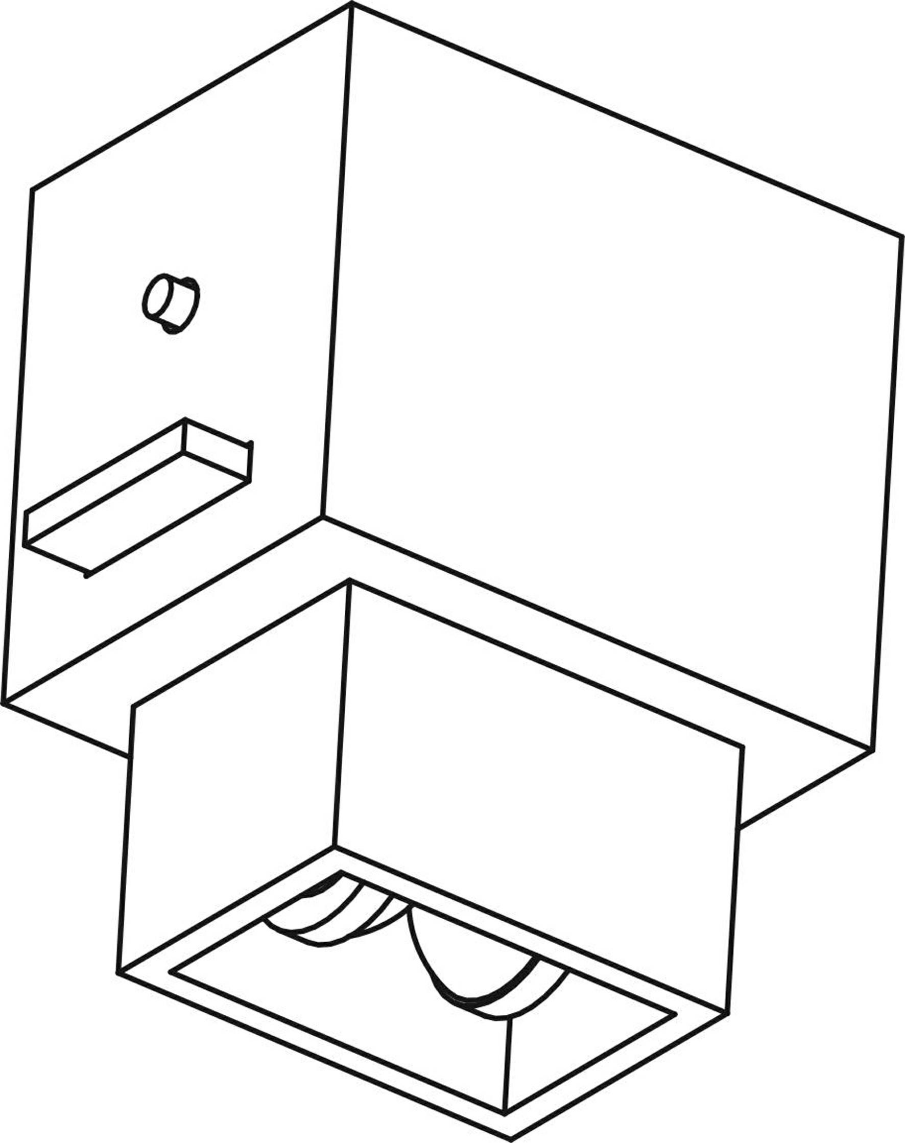
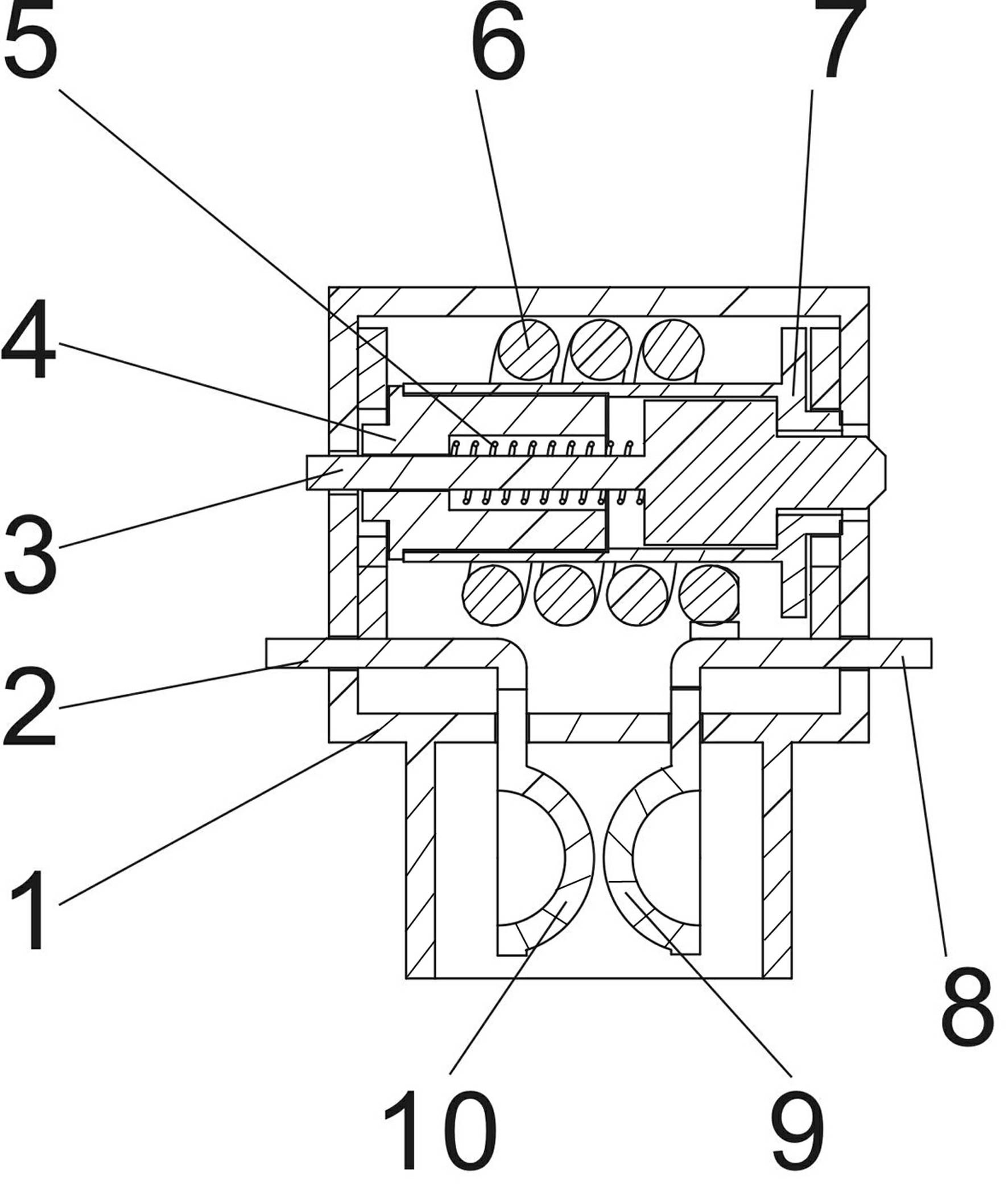
[0013] An electromagnet with a current sorting channel according to the present invention, such as figure 1 , 2 , 3, 4 shown, it comprises the electromagnet that is made up of moving iron core 3, static iron core 4, recovery spring 5, electromagnetic coil 6, a pair of hemispherical protruding parts facing each other in parallel at the two ends of electromagnetic coil 6 discharge electrode. image 3 Also marked with housing 1, left terminal 2, coil support 7, right terminal 8, right discharge electrode 9, left discharge electrode 10.

[0014] Figure 4 Among them, D is the moving iron core of the electromagnet, which can move along the direction of the arrow. L is the electromagnetic coil, A and B are the two ends of the coil channel, and S is the gap arrester. The power frequency current passes through A and reaches the terminal B through the electromagnetic coil L, and the moving iron core of the electromagnet moves quickly to achieve the purpose of driving. When the lig...


PUM


Abstract

The invention discloses an electromagnet with a current separation channel. The electromagnet comprises a movable iron core, a static iron core, a return spring and an electromagnetic coil. The electromagnet with the current separation channel is characterized in that a pair of discharging electrodes is connected with two ends of the electromagnetic coil in parallel. The electromagnet with the current separation channel, disclosed by the invention, has the beneficial effect of being capable of resisting scores of kiloamperes of lightning impulse current due to the addition of the current separation channel, thus the electromagnet can act under a small current to achieve a driving purpose and also can shunt a stronger current such that the service life of the electromagnet is prolonged.

Description

technical field [0001] The invention relates to an electromagnet, in particular to an electromagnet with a current sorting channel. Background technique [0002] Currently used in various miniature circuit breakers, the moving iron core of the electromagnet generates action according to the power frequency current passing through the coil. This power frequency current is also called the action current to achieve the purpose of driving. Ideally, for an electromagnet that outputs rated thrust, the smaller the driving power required, the better, that is, the smaller the operating current through the electromagnet coil, the better the effect. To reduce the operating current, the number of coil turns must be increased; the increase in the number of turns will reduce the diameter of the wire; the diameter of the coil is small, and the coil is easy to burn out when a large current comes. Contents of the invention [0003] The purpose of the present invention is to provide an ele...

Claims


Application Information

Patent Timeline
Patent Type & Authority Applications(China)
IPC IPC(8): H01H50/16
Inventor 李欣李柏林李博琛陈荣斌曾凡其
Owner XIAMEN TAIHANG TECH
Why Eureka
Try Eureka