
Winding mode of elevator steel wire rope and elevator

A wire rope and elevator technology, which is applied in the field of elevators, elevators or elevators, and can solve problems such as the deterioration of elevator operation performance

Inactive Publication Date: 2011-09-14
HANGZHOU OPTIMAX TECH
View PDF4 Cites 9 Cited by
  • Summary
  • Abstract
  • Description
  • Claims
  • Application Information

AI Technical Summary

Problems solved by technology

The new winding method of the steel wire rope or steel belt provided, specifically, the bending method of the steel wire rope or steel belt around the counterweight wheel and the steel wire rope around the traction sheave in the same direction, and the final installation and arrangement of the rope end combination on the vertical projection plane of the traction machine It can effectively and thoroughly solve the problems existing in the existing technology, mainly to solve the problems caused by the large number of wire ropes and the large number of counterweights after the application of the strip type traction machine. The problem of significant deterioration of elevator performance due to the use of wheels

Method used


Image

  • Winding mode of elevator steel wire rope and elevator
  • Winding mode of elevator steel wire rope and elevator
  • Winding mode of elevator steel wire rope and elevator

Examples


Embodiment Construction

[0022] Attached below Figure 1-8 The specific technical contents and embodiments of the present invention are further elaborated.

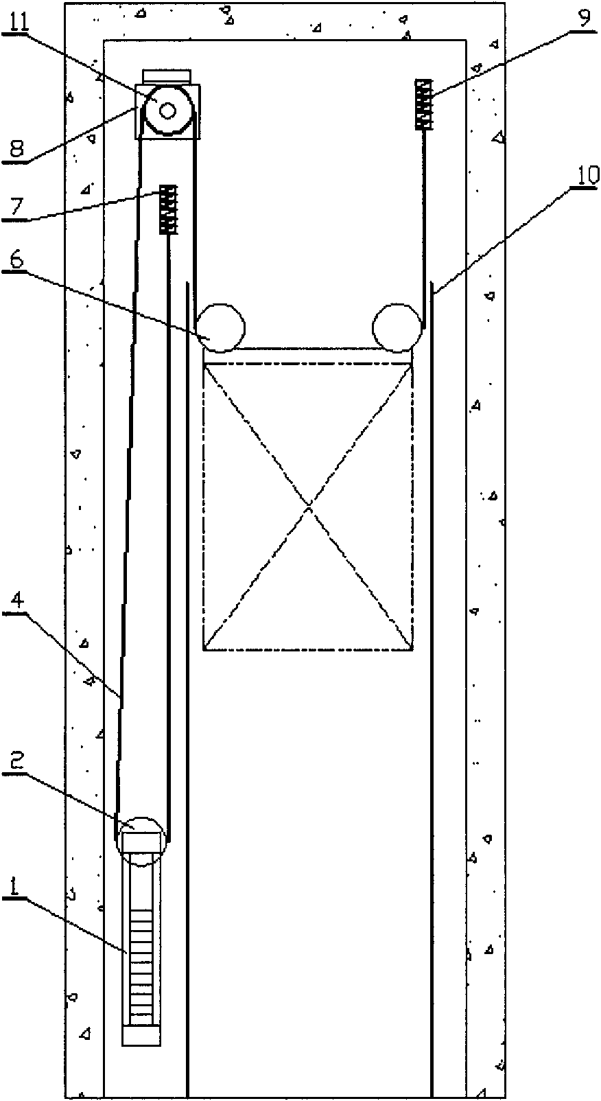
[0023] attached figure 1 , 2 Indicates an embodiment of the new winding method of the elevator wire rope or steel belt provided by the present invention and the new arrangement method of the rope end combination in the whole elevator, which mainly includes the counterweight device 1 of the elevator, two rows of counterweight guide rails 3, the steel wire rope Or steel belt 4, car 5, two car top wheels 6, counterweight side rope end combination 7, traction machine 8, car side rope end combination 9, two rows of car guide rails 10, wherein the counterweight The device 1 includes a counterweight, a counterweight wheel 2 and a counterweight frame, and the counterweight wheel 2 is arranged on the upper part of the counterweight device 1. The traction machine 8 includes a traction wheel 11 and a traction machine body. The traction machine 8 Arranged...


PUM


Abstract

The invention relates to a winding mode of an elevator steel wire rope and an elevator. The elevator comprises elevator parts, wherein a counterweight wheel (2) is arranged at the upper part of a counterweight device (1); a traction machine (8) is arranged above the counterweight device (1); the axis of a traction wheel (11) and the axis of the counterweight wheel (2) are arranged in parallel or at an included angle of 0 to 90 degrees in the positive and negative directions. After winding around two crosshead sheaves (6), the steel wire rope or a steel strip (4) is lifted to the traction machine (8) to bypass the traction wheel (11) in the anticlockwise direction, then is descended to the counterweight device (1) to bypass the counterweight wheel (2) in the anticlockwise direction, is lifted and finally is fixed on a counterweight side thimble rod rope socket (7). The counterweight side thimble rod rope socket (7) are arranged in three modes: 1, the counterweight side thimble rod rope socket (7) is arranged right below a vertical projection plane of the traction machine (8); 2, the counterweight side thimble rod rope socket (7) is arranged right below in a region that the vertical projection plane extends backwards along the depth direction of a shaft; and 3, the counterweight side thimble rod rope socket (7) is arranged right below in a region that the vertical projection plane extends forwards along the depth direction of the shaft. Due to the simple winding mode, the stripe traction machine can be widely applied to the elevator without a machine room, the elevator with the machine room or other types of elevators.

Description

technical field [0001] The invention relates to an elevator wire rope winding method and an elevator, specifically including a new winding method of an elevator wire rope or a steel belt, a new arrangement method of a combination of rope heads, and an elevator or elevator obtained thereby, belonging to the category of elevators. Background technique [0002] When the traditional elevator wire rope goes down from the traction sheave to the counterweight device and bypasses the counterweight wheel, it goes around the counterweight wheel in the opposite direction to when the wire rope goes around the traction sheave. This winding method of the elevator wire rope is generally in the After passing around the counter rollers, the rope end assembly is usually installed in the area between the traction machine and its adjacent side wall. In recent years, with the gradual application of small-diameter steel wire ropes and steel belts, bar-shaped traction machines have been introduced...

Claims


Application Information

Patent Timeline
Patent Type & Authority Applications(China)
IPC IPC(8): B66B7/06
Inventor 胡建友金来生
Owner HANGZHOU OPTIMAX TECH
Learn More