
Electronic device taking hook structure as wireless signal transceiving antenna

A technology for wireless signals and electronic devices, applied in the field of electronic devices, can solve problems such as the overall bulkiness of electronic devices, breakage, and increase in size and thickness of electronic devices, and achieve the effects of reducing component costs and flexibly using space.

Inactive Publication Date: 2011-09-07
MITAC PRECISION TECH(KUNSHAN) CORP
View PDF6 Cites 2 Cited by
  • Summary
  • Abstract
  • Description
  • Claims
  • Application Information

AI Technical Summary

Problems solved by technology

[0006] However, the configuration of the wireless signal transmitting and receiving antenna will affect the structural design of the electronic device itself
The design of the wireless signal transmitting and receiving antenna extending from the main body often results in a relative increase in the size and thickness of the electronic device, making the overall electronic device relatively large, which does not meet the requirements of modern people's pursuit of lightness, thinness and shortness.
Furthermore, the swing-out design of the wireless signal receiving and transmitting antenna will easily be damaged by external force collisions because it is exposed outside the body of the electronic device, and it is necessary to reserve some screw-out space when the wireless signal transmitting and receiving antenna is screwed out.
[0007] As for the design of embedding the wireless signal transmitting and receiving antenna in the body of the electronic device, because there must be a space for the wireless signal transmitting and receiving antenna, there are often obvious protrusions on the appearance of the product, which is not only difficult to look good in appearance, but also easy to Causes rupture damage when dropped or impacted by external force
However, accommodating the wireless signal transmitting and receiving antennas in the hooks, handles, etc. of the electronic device does not occupy the internal space of the electronic device, but it is also easy to make the hooks, handles, etc. more bulky, and the The wireless signal transmitting and receiving antenna is wrapped in the structure, which will affect the transmitting and receiving effect of the wireless signal transmitting and receiving antenna

Method used


Image

  • Electronic device taking hook structure as wireless signal transceiving antenna
  • Electronic device taking hook structure as wireless signal transceiving antenna
  • Electronic device taking hook structure as wireless signal transceiving antenna

Examples


Embodiment Construction

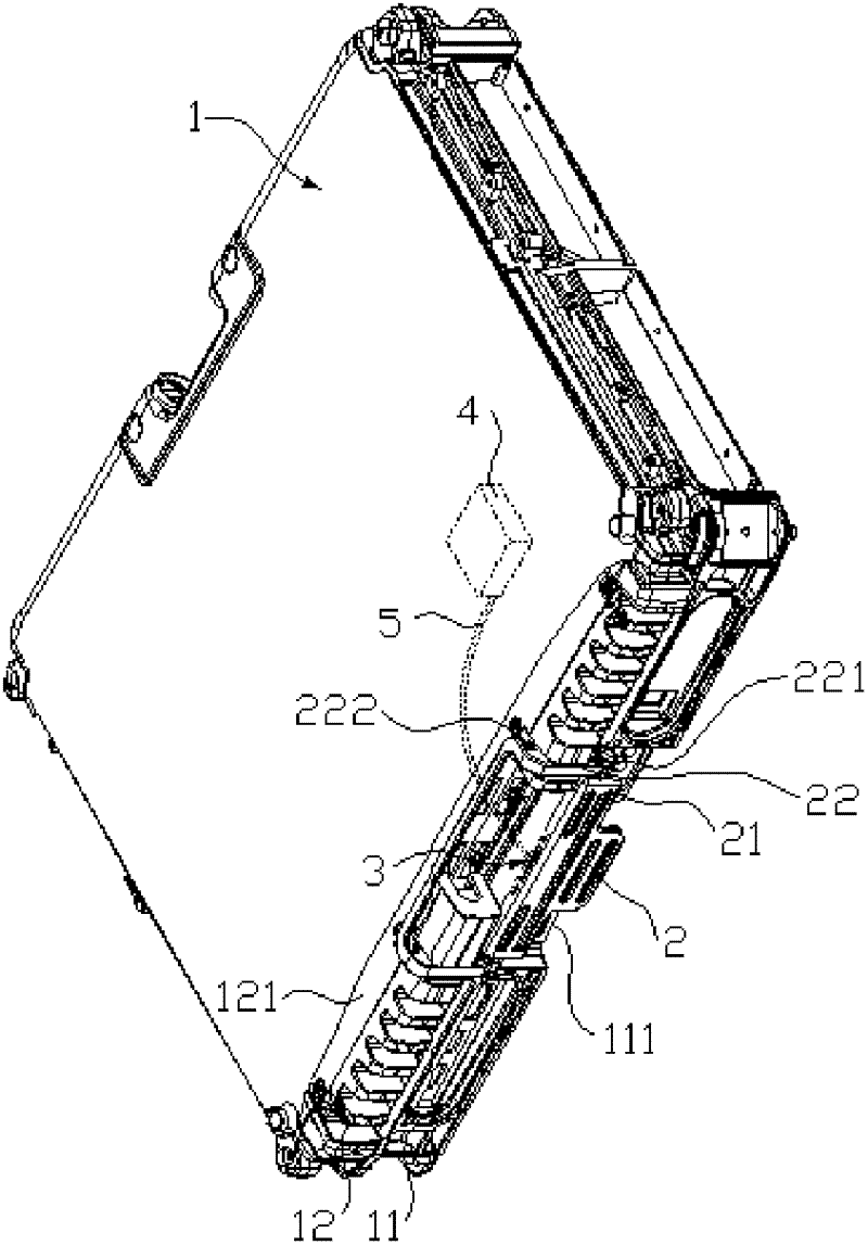
[0023] refer to figure 1 As shown, it is a perspective view of the first embodiment of the present invention. As shown in the figure, the electronic device 1 includes two pairs of covers 11 , 12 , and a hook structure 2 combined with the electronic device 1 . In this embodiment, the electronic device 1 is a notebook computer, and the covers 11 and 12 are respectively the display part and the host part of the notebook computer. The covers 11 and 12 can be opened or closed. The hook structure 2 is combined with the end edge 111 of the cover 11 of the electronic device 1 through a connecting structure 3 , of course, it can also be combined with the end edge 121 of another cover 12 , depending on the design.

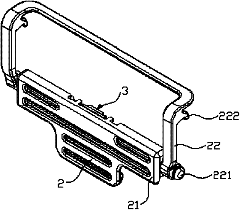
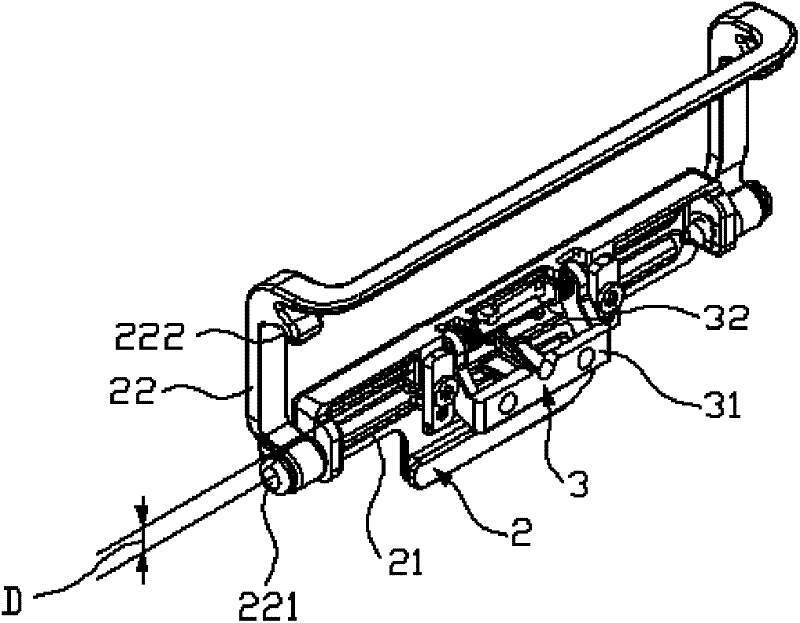
[0024] refer to Figure 2 to Figure 3 As shown, it is a front perspective view of the hook structure of the first embodiment of the present invention, and a rear perspective view of the hook structure of the first embodiment of the present invention. The hook structure 2 ...


PUM


Abstract

The invention provides an electronic device taking a hook structure as a wireless signal transceiving antenna, comprising two pairs of closed cover bodies and at least one hook structure, wherein the hook structure is combined with an end edge of a cover body of the electronic device by a connecting member. When the two cover bodies of the electronic device are closed, the two cover bodies are buckled. The hook structure is made from conducting materials or provided with at least one metal conducting part. The electronic device is characterized in that one wireless signal transceiving module in the electronic device is an antenna feed line which passes through the connecting member, and electrically connected with the hook structure made from the conducting materials or the metal conducting part of the hook structure; and the hook structure is taken as the wireless signal transceiving antenna of the wireless signal transceiving module.

Description

【Technical field】 [0001] The invention relates to a hook structure, in particular to an electronic device using the hook structure as a wireless signal transmitting and receiving antenna. 【Background technique】 [0002] An electronic device with a built-in wireless transmission function is usually provided with a wireless signal transmitting and receiving antenna in an accommodating slot on a side or top side of a notebook computer in a manner that can be moved out or stored. As for the products installed inside, they are buried on the rear side, two sides or the top side of the notebook computer display, or are buried at the hinge where the host computer and the display are pivotally connected. [0003] Taiwan Patent Publication No. 465810 patent case, which provides an antenna device configured at an appropriate position of an openable and closable cover of a portable electronic data processor, which includes an accommodating a component; it is arranged in the containing ...

Claims


Application Information

Patent Timeline
Patent Type & Authority Applications(China)
IPC IPC(8): H01Q1/44H01Q1/24G06F1/16
Inventor 林煌斌
Owner MITAC PRECISION TECH(KUNSHAN) CORP
Learn More