High-power pseudo-spark switch tube for power electronic pulse conversion
A technology of power electronics and spark switch, applied in thermionic cathode tubes, etc., can solve the problems of long delay time, difficult output waveform of frequency conversion speed regulation system, etc., achieve the effects of small trigger power, solve trigger speed, and high repetition frequency
- Summary
- Abstract
- Description
- Claims
- Application Information
AI Technical Summary
Problems solved by technology
Method used
Image


Examples
Embodiment 1
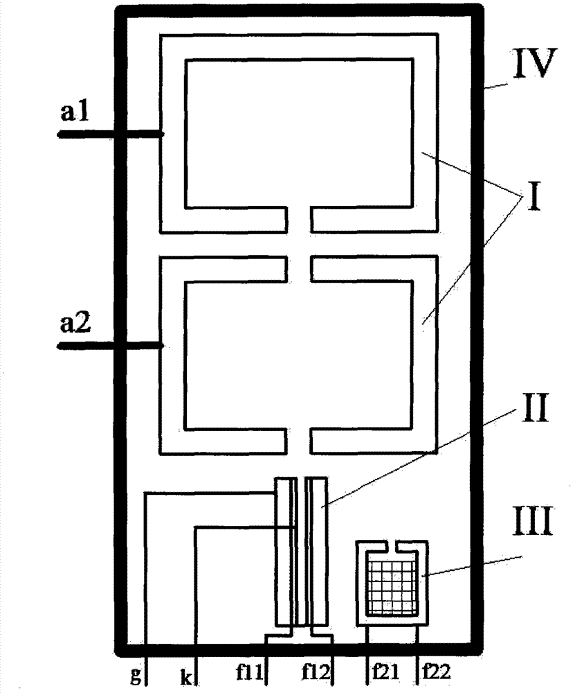
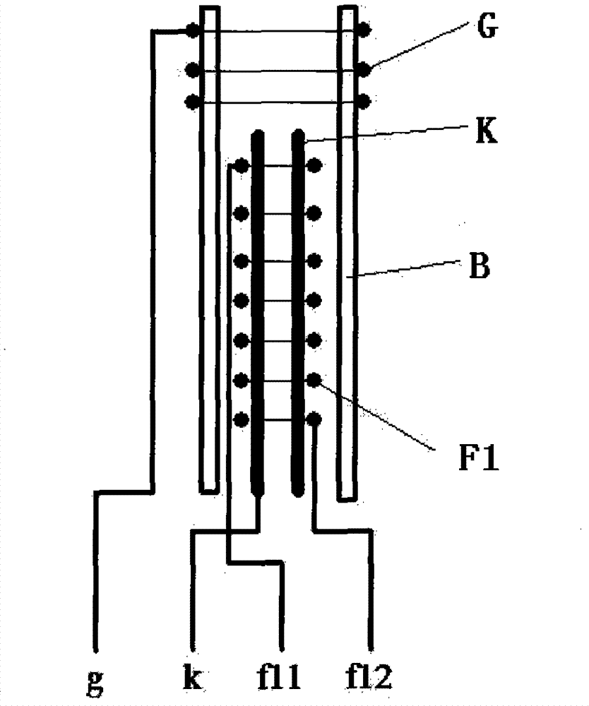
[0016] Embodiment 1: as attached figure 1 , 2 , 3, 4 and 5, the high-power spark switch tube consists of a ceramic sealed tube body IV and the main electrode unit I contained therein, the trigger electron gun unit II, the hydrogen storage unit III, and an external circuit. The main electrode unit Ⅰ is installed in the upper middle part of the sealed ceramic tube body Ⅳ. It is composed of two stainless steel coaxial hollow cylinders with double ends closed, the end faces parallel and kept at a certain distance, and their electrical leads. The upper and lower cylinders are respectively The first anode A1 and the second anode A2, the center of the lower end surface of the first anode A1 has a circular hole d 11 , the center positions of the upper and lower ends of the second anode A2 are respectively opened with a garden hole d 21 and d 22 , hole d 11 with d 21 are equal in diameter and are 1.5mm, d 22 The hole diameter of the two cylindrical electrodes is 1mm, the inner di...
Embodiment 2
[0017] Embodiment 2: as attached figure 1 , 2 , 3, 4 and 5, the high-power spark switch tube consists of a glass sealed tube body Ⅳ and the main electrode unit Ⅰ, the trigger electron gun unit Ⅱ, the hydrogen storage unit Ⅲ, and the external circuit. The main electrode unit Ⅰ is installed in the upper middle part of the sealed glass tube body Ⅳ. It is composed of two stainless steel coaxial hollow cylinders with double ends closed, the end faces parallel and keeping a certain distance, and their electrical leads. The upper and lower cylinders are respectively The first anode A1 and the second anode A2, the center of the lower end surface of the first anode A1 has a circular hole d 11 , the center positions of the upper and lower ends of the second anode A2 are respectively opened with a garden hole d 21 and d 22 , hole d 11 with d 21 are equal in diameter and are 9mm, d 22 The hole diameter of the two cylindrical electrodes is 10mm, the inner diameter of the two cylindri...
Embodiment 3
[0018] Embodiment 3: as attached figure 1 , 2 , 3, 4 and 5, the high-power spark switch tube consists of a ceramic sealed tube body IV and the main electrode unit I contained therein, the trigger electron gun unit II, the hydrogen storage unit III, and an external circuit. The main electrode unit Ⅰ is installed in the upper middle part of the sealed ceramic tube body Ⅳ. It consists of two coaxial hollow cylinders (made of stainless steel) with closed double ends, parallel end faces and a certain distance between them and their electrical leads. The lower cylinders are respectively the first anode A1 and the second anode A2, and the center of the lower end surface of the first anode A1 has a circular hole d 11 , the center positions of the upper and lower ends of the second anode A2 are respectively opened with a garden hole d 21 and d 22 , hole d 11 with d 21 are equal in diameter and are 3mm, d 22 The hole diameter of the two cylindrical electrodes is 4mm, the inner dia...
PUM
 Abstract
Description
Claims
Application Information
 - Generate Ideas
- Intellectual Property
- Life Sciences
- Materials
- Tech Scout
- Unparalleled Data Quality
- Higher Quality Content
- 60% Fewer Hallucinations
Browse by: Latest US Patents, China's latest patents, Technical Efficacy Thesaurus, Application Domain, Technology Topic, Popular Technical Reports.
© 2025 PatSnap. All rights reserved.Legal|Privacy policy|Modern Slavery Act Transparency Statement|Sitemap|About US| Contact US: help@patsnap.com