
Photovoltaic grid-connected inverter test bench

A test platform and inverter technology, which is applied in the direction of instruments, measuring electricity, and measuring devices, can solve the problems of large footprint, inability to detect the performance of photovoltaic grid-connected inverters and power grids, and waste of electric energy, so as to reduce The effect of small power loss

Inactive Publication Date: 2011-09-07
FUDAN UNIV
View PDF7 Cites 53 Cited by
  • Summary
  • Abstract
  • Description
  • Claims
  • Application Information

AI Technical Summary

Problems solved by technology

[0003] However, when testing the inverter at present, the input source of the inverter usually uses a real photovoltaic cell array or a DC analog power supply, which will bring various uncontrollable factors such as light conditions, ambient temperature, and wind speed. The cost of photovoltaic array is high, and the installation and maintenance are very inconvenient. The load on the output side of the inverter is usually composed of a high-power resistor and an AC voltage stabilizer. The working performance in the waveform state, but the device is a voltage source. In terms of circuit structure and design framework, it is impossible to realize the working state of bidirectional four-quadrant current source and voltage source in one device at the same time, and the output power of the inverter cannot be reversed. It is sent to the power grid, but directly consumed through resistance, which on the one hand causes a lot of waste of electric energy, and on the other hand, it is impossible to detect the performance of the four-quadrant working state of current / voltage between the photovoltaic grid-connected inverter and the grid

Method used


Image

  • Photovoltaic grid-connected inverter test bench
  • Photovoltaic grid-connected inverter test bench
  • Photovoltaic grid-connected inverter test bench

Examples


Embodiment Construction

[0018] Below in conjunction with accompanying drawing and example, the present invention is described in further detail.

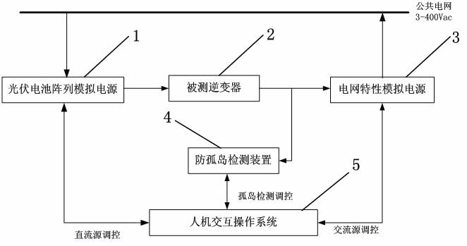
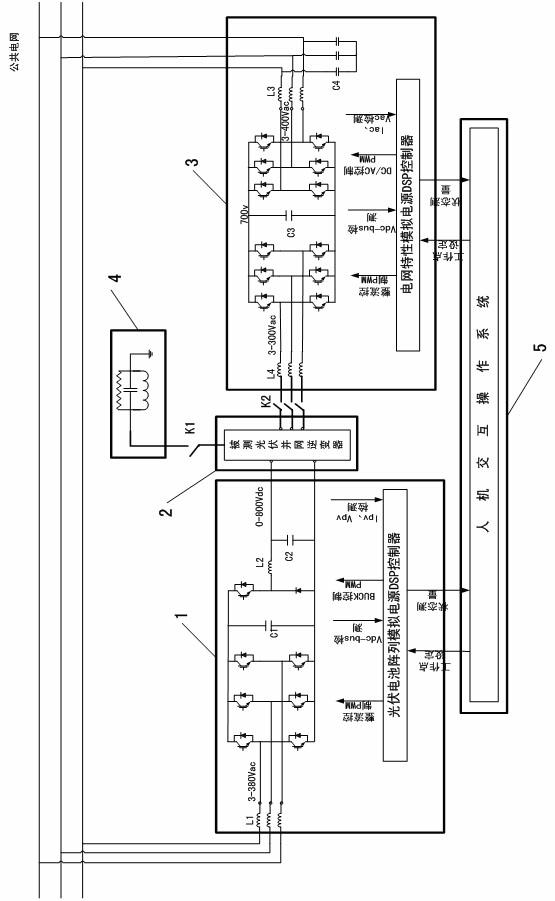
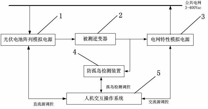
[0019] see Figure 1~2 , the present invention is composed of a photovoltaic cell array simulation power supply 1 , a power grid characteristic simulation power supply 3 , an anti-islanding detection device 4 , a human-computer interaction operating system 5 and a photovoltaic grid-connected inverter 2 to be tested. Photovoltaic cell array simulation power supply 1 is used as the input source of the tested inverter 2, simulating the real photovoltaic cell array; grid characteristic simulation power supply 3 is connected to the output terminal of the tested inverter 2, and the grid-connected characteristics of the inverter 2 are detected ; The anti-islanding detection device 4 passes through the switch K1 (such as figure 2 shown) is connected to the inverter 2 under test for testing the islanding protection performance of the inverter 2; the human-compute...


PUM


Abstract

The invention belongs to the technical field for testing photovoltaic grid-connected inverters, in particular to a test bench for testing various performance indexes of a photovoltaic grid-connected inverter. The test bench uses a photovoltaic battery array simulating power supply as the input source of the inverter so to displace the original real photovoltaic battery array, and uses a grid characteristic stimulating power supply to displace a large-power resistor load. The photovoltaic battery array simulating power supply can set the needed weather conditions like illumination, environment temperature, wind speed and the like conveniently, output a V-I (voltage-current) curve conforming to the requirements, and overcome the shortages that the real photovoltaic battery array has multiple uncontrollable factors and the installation and maintenance are not convenient. The grid characteristic stimulating power supply can simulate the characteristics like a grid voltage, a frequency, background harmonic waves and the like, can detect the working performances of the inverter under different grid states, and can feed back the output electric energy of the inverter to a public grid, so that the electric energy loss is reduced.

Description

technical field [0001] The invention belongs to the technical field of testing photovoltaic grid-connected inverters, and in particular relates to a testing platform for photovoltaic grid-connected inverters. Background technique [0002] Today, with energy depletion and environmental pollution becoming more and more serious, photovoltaic power generation technology has become a new energy technology that countries all over the world are vying to develop. The photovoltaic grid-connected inverter is the core component of the photovoltaic power generation system, and its performance is related to the utilization rate, reliability and power supply quality of the photovoltaic system. Therefore, it is necessary to have a comprehensive test platform that can detect various performance indicators of grid-connected inverters and ensure that the performance of the inverters meets relevant standards. [0003] However, when testing the inverter at present, the input source of the inve...

Claims


Application Information

Patent Timeline
IPC IPC(8): G01R31/00
Inventor 孙耀杰林燕丹钱敏华范瑞祥童立青
Owner FUDAN UNIV
Learn More