Combine harvesting machine
What is Al technical title?
Al technical title is built by PatSnap Al team. It summarizes the technical point description of the patent document.
A combine harvester and frame technology, applied to harvesters, cutters, agricultural machinery and implements, etc., can solve the problems of many transmission chains, low purchasing power, inconvenient transportation, etc., and achieve the goal of reducing weight, length and drum Volume, the effect of reducing the weight of the machine
Inactive Publication Date: 2012-12-19
何嘉俊
View PDF0 Cites 0 Cited by
Summary
Abstract
Description
Claims
Application Information
AI Technical Summary
This helps you quickly interpret patents by identifying the three key elements:
Problems solved by technology
Method used
Benefits of technology
Problems solved by technology
In this process, not only the distance is long, but also because of the many transmission chains, the structure is complex, the energy consumption is high, and the quality is heavy, which is not suitable for the situation in some areas of our country where the field area is small, the transportation is inconvenient, and the purchasing power is low.
Method used
Image
Click on the blue label to locate the original text in one second.
Reading with bidirectional positioning of images and text.
Examples
Embodiment Construction
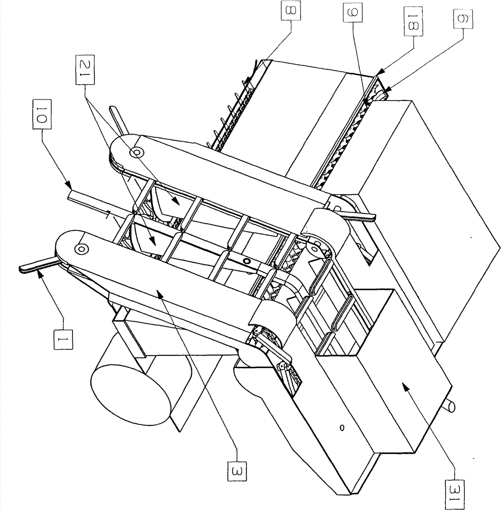
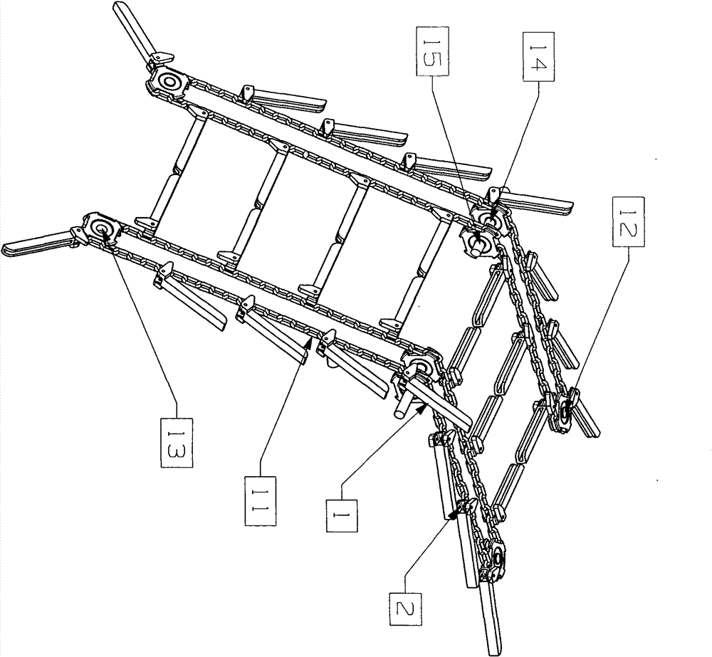
[0034] The present invention will be described in further detail below in conjunction with the accompanying drawings and specific embodiments.
[0035] figure 1 It is a schematic diagram of the structure of the first type of combine harvester, figure 2 It is a schematic diagram of the structure of the fuhe finger, the fuhe finger seat and the ring link, image 3 It is a schematic diagram of the cooperation between the Fuhe finger, the Fuhe finger seat and the endless chain chain, Figure 4 Schematic diagram of the structure of the bottom plate, Figure 5 A schematic diagram of the structure of the upper cover, Image 6 It is a schematic diagram of the structure of the grain-supporting mechanism installed on the frame in the first type of combine harvester, Figure 7 It is a structural schematic diagram of the grass discharge chain, the clamping conveyor chain and the threshing drum installed on the frame in the first type of combine harvester, as shown in the figure. The...
PUM
Abstract
The invention discloses a combine harvesting machine which comprises a clamping chain press block, a threshing roller, a grass discharge chain, a clamping delivering chain, a seedling dividing bar, stalk cutters, a seedling drawing star wheel, spike bending bars, a machine frame and a seedling holding mechanism; the seedling holding mechanism comprises a seedling holding finger, a seedling holding finger seat, an upper bending cover plate, a lower bending base plate, an annular chain, a driving chain wheel, a driven chain wheel, a left bending chain wheel and a right bending chain wheel. Meanwhile, the invention also provides a combine harvesting machine which can realize full feeding of spikes. In the invention, a seedling holding and spike bending mechanism is used on a semi-feeding combine harvesting machine, a conveying distance of harvest crops into the roller is shortened, spikes are introduced into the roller in order, a transmission chain of the combine harvesting machine is simplified, and the weight of the harvesting machine and the energy consumption of the whole machine are reduced; By the combine harvesting machine which can realize full feeding of the spikes, accurate crop spikes harvesting can be realized, the quantity of leaves and stalks introduced into the threshing roller is greatly reduced, the length of the transmission chain and the volume of the roller are shortened, and the energy consumption and the weight of the machine are reduced.
Description
technical field [0001] The invention relates to a combine harvester. Background technique [0002] In the prior art, a combine harvester includes a clamping chain briquetting block, a threshing drum, a grass discharge chain, a clamping conveying chain, a splitting stalk, a stalk cutter, a reeling star wheel, a crop guide plate, a guide plate, Rack and Fuhe mechanism. The grain-holding mechanism includes a roller chain (or a snap-finger reel), a grain-holding finger, a grain-holding finger seat, an upper cover plate and a lower bottom plate. The lower base plate is installed on the frame, the top of the lower base plate is equipped with a contraction limit shaft, the bottom of the upper cover plate is equipped with an extension limit block, and the upper cover plate is fastened on the lower base plate. The inner end of the upper cover plate and the lower bottom plate is provided with a limit plate for the holding finger seat, and the outer end is provided with a retractable...
Claims
Application Information
Patent Timeline
Application Date:The date an application was filed.
Publication Date:The date a patent or application was officially published.
First Publication Date:The earliest publication date of a patent with the same application number.
Issue Date:Publication date of the patent grant document.
PCT Entry Date:The Entry date of PCT National Phase.
Estimated Expiry Date:The statutory expiry date of a patent right according to the Patent Law, and it is the longest term of protection that the patent right can achieve without the termination of the patent right due to other reasons(Term extension factor has been taken into account ).
Invalid Date:Actual expiry date is based on effective date or publication date of legal transaction data of invalid patent.