Cross-flow filtration apparatus with biocidal feed spacer
A technology of cross-flow filtration and feeding, which is applied in the direction of membrane, membrane technology, chemical instruments and methods, etc. It can solve the problems of loss of production capacity, easy fouling of cross-flow filter system, inability to allow backwash to remove solids, etc.
- Summary
- Abstract
- Description
- Claims
- Application Information
AI Technical Summary
Problems solved by technology
Method used
Image
Examples
Embodiment 1
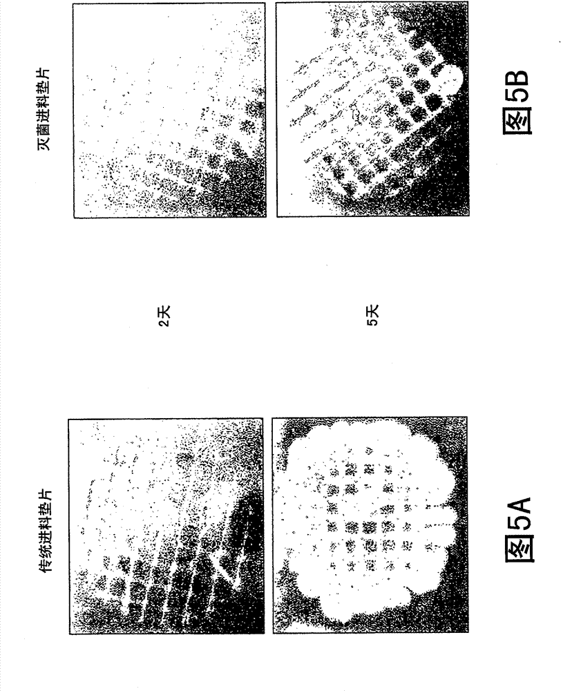
[0052] Sterile feed gaskets were fabricated by extruding a polypropylene-based resin mixed with about 0.5% by weight triclosan by an extrusion process. A portion of the sterile feed spacer was then excised and placed in a nutrient matrix (ie, an agar plate) inoculated with common bacteria. Feed gaskets manufactured in the same manner as the sterile feed gaskets were manufactured, except that the sterilizing agent triclosan was included, were used as control samples. A portion of the control feed spacer was placed in a nutrient matrix inoculated with common bacteria. Figure 5A Bacterial growth on control feed pads after 2 and 5 days is shown. Figure 5B Bacterial growth on sterile feed spacers after 2 and 5 days is shown. Such as Figure 5A and 5B As shown, the growth of bacteria on the sterilized feed pads was significantly less than that on the control feed pads after 2 and 5 days.
Embodiment 2
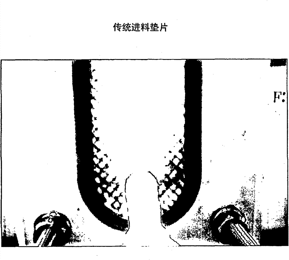
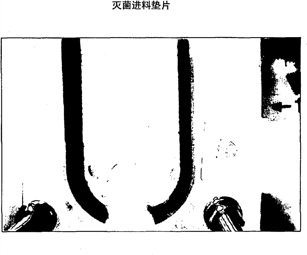
[0054] The same sterile and control feed spacers as in Example 1 were used in the laboratory flow analysis. Such as Figure 6A and 6B As shown, both feed spacers were connected to a waste water feed stream at a flow rate of 0.5 L / min for one month. Such as Figure 6A and 6B As shown, the bacteria in the sterilized feed gasket ( Figure 6B ) growth was significantly less than that on the control feed gasket ( Figure 6A ) on the growth.
Embodiment 3
[0056] In a water filtration plant known to have a high rate of biofouling, a reverse osmosis filter fabricated as in Example 1 with a 0.8 mm thick sterile feed gasket was evaluated and compared with A conventional reverse osmosis filter with a 0.8mm thick feed gasket was used for comparison. These reverse osmosis filters were placed in the facility's water filtration system for 6 months as the lead element (ie, the first element in a series of elements receiving a flow of feed solution). The two reverse osmosis filters were then evaluated for pressure drop and biofilm formation.
[0057] The reverse osmosis filter with the sterilized feed gasket showed a filter pressure drop of 7.3 psi, while the conventional reverse osmosis filter showed a pressure drop of 11 psi. An increase in filter pressure drop is directly related to an increase in RO filter biofouling. In addition, if Figure 7A and 7B As shown, compared with the traditional reverse osmosis filter ( Figure 7A ) c...
PUM
 Abstract
Description
Claims
Application Information
 - R&D Engineer
- R&D Manager
- IP Professional
- Industry Leading Data Capabilities
- Powerful AI technology
- Patent DNA Extraction
Browse by: Latest US Patents, China's latest patents, Technical Efficacy Thesaurus, Application Domain, Technology Topic, Popular Technical Reports.
© 2024 PatSnap. All rights reserved.Legal|Privacy policy|Modern Slavery Act Transparency Statement|Sitemap|About US| Contact US: help@patsnap.com


