Device and method for detecting rich-Te phase in telluride semiconductor crystal
A semiconductor and telluride technology, used in the field of detection devices, can solve the problems of difficult to obtain size, large field of view, and inability to achieve layered domain focusing imaging.
- Summary
- Abstract
- Description
- Claims
- Application Information
AI Technical Summary
Problems solved by technology
Method used
Image
Examples
Embodiment 1
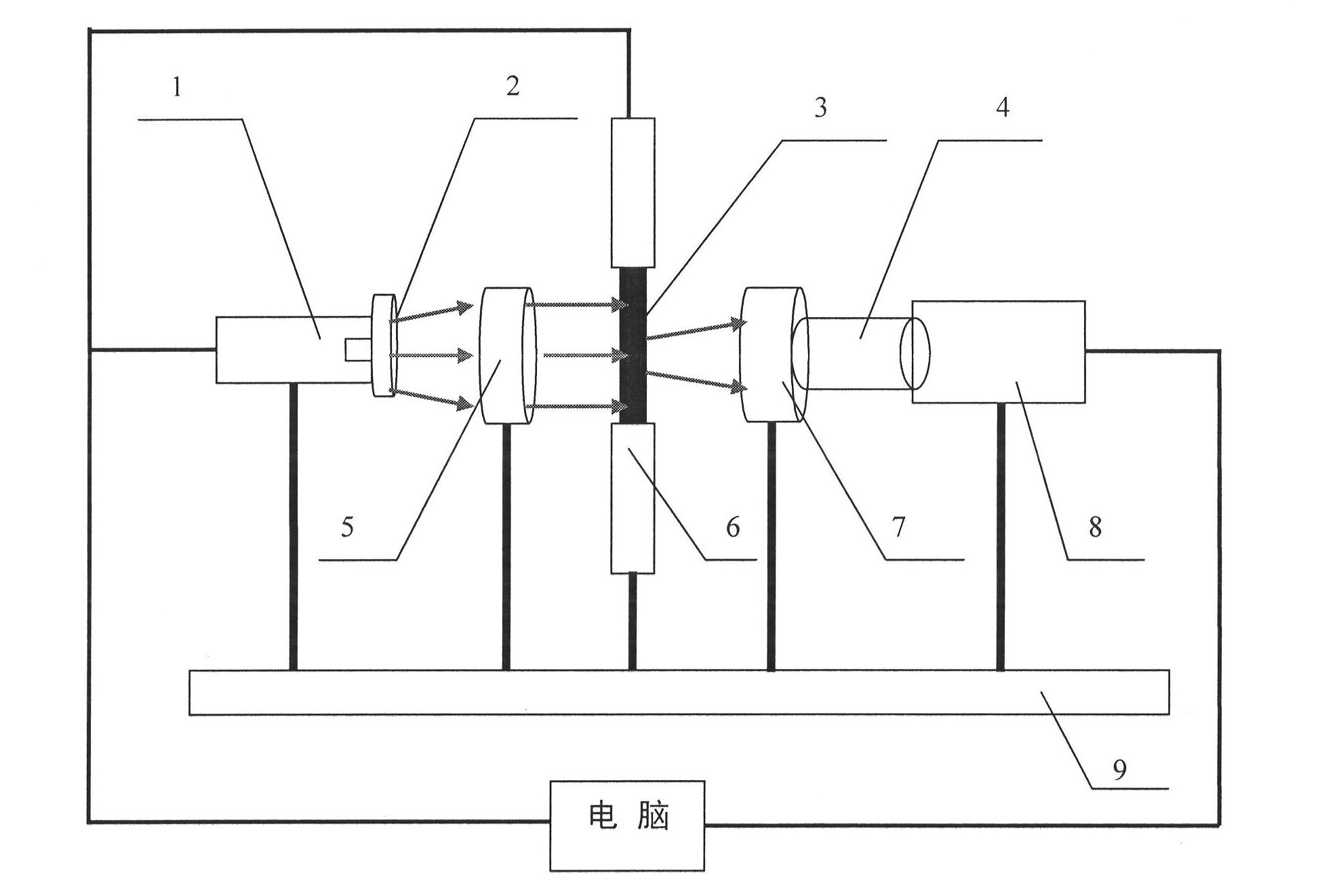
[0028] Embodiment 1 (device embodiment): The device for detecting the Te-rich phase in telluride semiconductor crystals of the present invention includes a light source 1, a lens 2, a lens barrel 4, an optical filter 5, a stage 6, an objective lens 7 and an infrared CCD 8. Among them, the light source 1 uses a halogen tungsten lamp with a spectral range of 360-2000nm as the radiation source for illuminating the crystal 3, and is fixed on one end of the optical vibration isolation platform 9 through a support rod, and the intensity of the light source 1 is controlled by a computer. A lens 2 is placed at the output end of the light source 1, and the focusing degree of light can be adjusted by changing the distance between the lens 2 and the light source 1. A filter 5 is placed behind the lens 2 and fixed on an optical vibration isolation platform 9 with a support rod to obtain monochromatic light for illuminating the sample. The stage 6 is a three-dimensional automatic translati...
Embodiment 2
[0030] Example 2: The detection size is 10×10×2mm 3 The size, shape and density of Te-rich phase particles in the CdZnTe crystal. Proceed as follows:
[0031] (a) Turn on the power of light source 1 and infrared CCD8, and preheat for 20 minutes, so that the output light intensity is stable, and the imaging noise and chromatic aberration of infrared CCD8 are small. At the same time, select the filter 5 with a wavelength of 980nm.
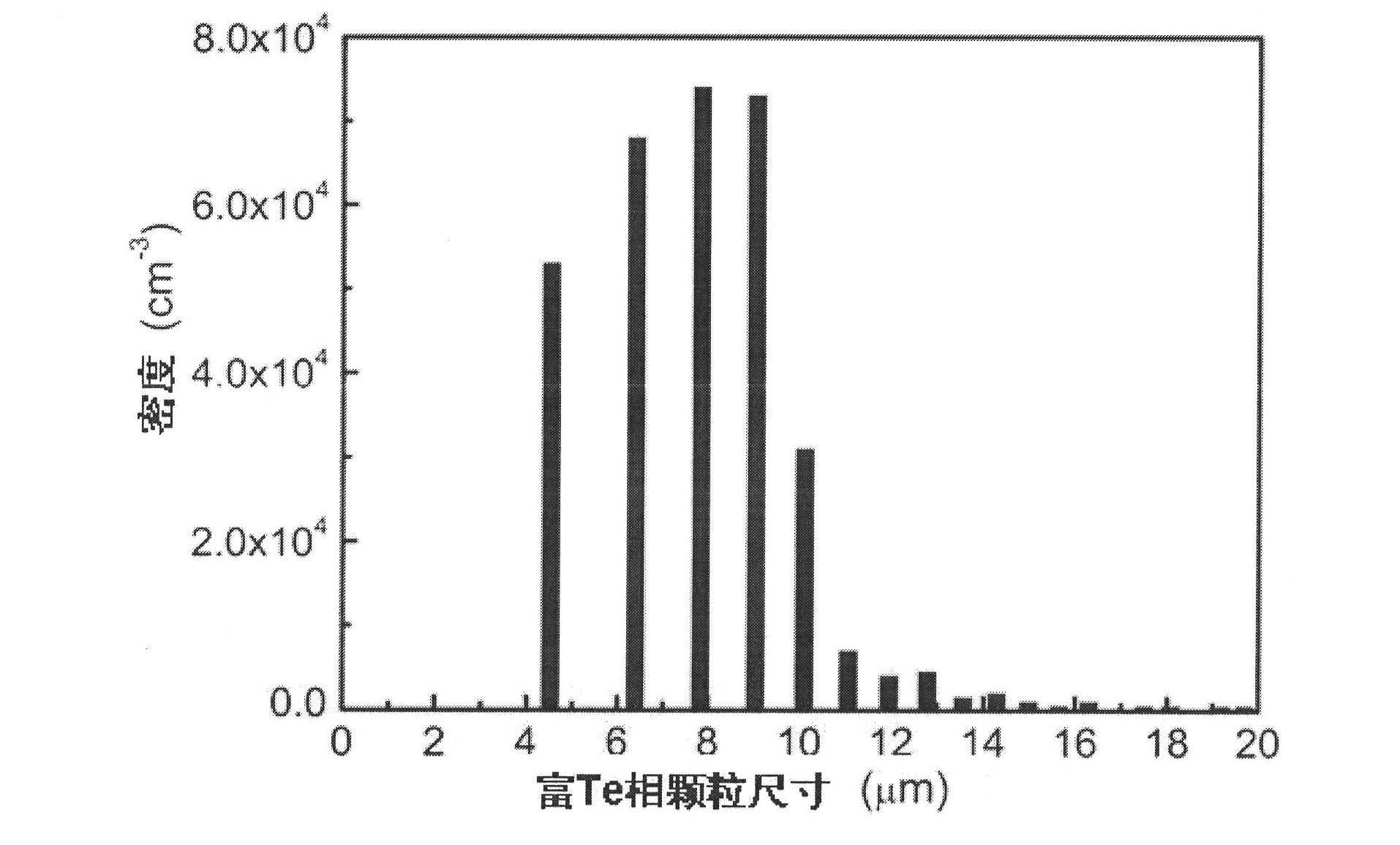
[0032] (b) Fix the processed CdZnTe crystal 3 on the stage 6, adjust the power output current of the light source 1 to 5.9A, and the luminous flux to be 1450lm, and move the position of the lens 2 horizontally, so that the image gray value collected by the infrared CCD 8 is between 150. The positions of the X, Y and R axes on the stage 6 are adjusted so that the beam line irradiates the CdZnTe crystal 3 to be tested vertically. At the same time, adjust the CdZnTe crystal 3 to be tested, the infrared objective lens 7, and the centers of the infrare...
Embodiment 3
[0037] Embodiment 3: The detection size is 10×10×2mm 3 The size, shape and density of Te-rich phase particles in CdTe crystals. Proceed as follows:
[0038] (a) Turn on the power of light source 1 and infrared CCD8, and preheat for 20 minutes, so that the output light intensity is stable, and the imaging noise and chromatic aberration of infrared CCD8 are small. At the same time, select the filter 5 with a wavelength of 980nm.
[0039] (b) Fix the processed CdTe crystal 3 on the stage 6, adjust the power output current of the light source 1 to 6.4A, and the luminous flux to 1550lm, and move the position of the lens 2 horizontally so that the gray value of the image collected by the infrared CCD 8 reaches 125. Adjust the positions of the X, Y axes and the rotation R axis in the stage 6 to ensure that the beam line irradiates the CdTe crystal 3 to be tested vertically. At the same time, adjust the center of the CdTe crystal 3 to be tested, the infrared light objective lens 7,...
PUM
| Property | Measurement | Unit |
|---|---|---|
| size | aaaaa | aaaaa |
Abstract
Description
Claims
Application Information
 - Generate Ideas
- Intellectual Property
- Life Sciences
- Materials
- Tech Scout
- Unparalleled Data Quality
- Higher Quality Content
- 60% Fewer Hallucinations
Browse by: Latest US Patents, China's latest patents, Technical Efficacy Thesaurus, Application Domain, Technology Topic, Popular Technical Reports.
© 2025 PatSnap. All rights reserved.Legal|Privacy policy|Modern Slavery Act Transparency Statement|Sitemap|About US| Contact US: help@patsnap.com


